Honda Odyssey 2004. Manual - part 24


  Index      Honda     Honda Odyssey 2004 - service repair manual 2004 year


Search            


Content   ..  22  23  24  25   ..


Honda Odyssey 2004. Manual - part 24


±

01

*01

S0X4A00A26100000000MAAT00
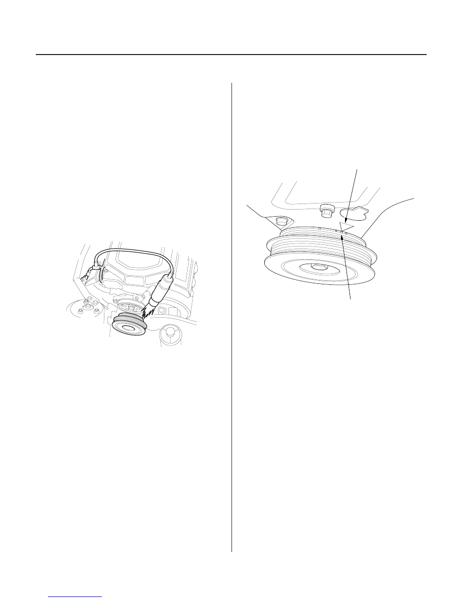
Ignition Timing:
10°

2° BTDC (RED mark (B)) during idling in Park

or Neutral

4-16

Ignition System

Ignition Timing Inspection

A

B

1. Connect the Honda Diagnostic System (HDS) to the

data link connector (DLC) (see step 2 on page 11-3),
and check for DTC’s. If a DTC is present, diagnose
and repair the cause before inspecting the ignition
timing.

2. Start the engine. Hold the engine at 3,000 rpm with

no load shift lever in Park or Neutral, until the
radiator fan comes on, then let it idle.

3. Check the idle speed, and adjust it if necessary (see

page 11-201).

4. Follow the tester’s prompts to get the tester in the

‘‘SCS’’ mode (see the tester operator’s manual).

5. Connect the timing light to the No. 1 ignition coil

wire.

6. Aim the light toward the pointer (A) on the timing

belt cover. Check the ignition timing under a no
load conditions: headlights, blower fan, rear
window defogger, and air conditioner are not
operating.

7. If the ignition timing differs from the specification,

check the cam timing, and the top dead center
(TDC) and crankshaft position (CKP) sensors. If
necessary, substitute a known-good powertrain
control module (PCM) and recheck (see page 11-5).

8. Turn the ignition switch OFF.

9. Disconnect the HDS and the timing light.

03/07/29 09:07:24 61S0X050_040_0016

01

02

11

S0X4A00A26100034101KDAT00

1999-2001 models:

2002-2004 models:

4-17

Ignition Coil Removal/Installation

A

B

B

6 x 1.0 mm
12 N·m
(1.2 kgf·m, 8.7 lbf·ft)

6 x 1.0 mm
12 N·m (1.2 kgf·m,
8.7 lbf·ft)

B

A

6 x 1.0 mm
12 N·m (1.2 kgf·m,
8.7 lbf·ft)

1. Remove the intake manifold cover (A) and ignition

coil cover(s) (B).

2. Disconnect the ignition coil connectors, then

remove the ignition coils.

3. Install the ignition coil in the reverse order of

removal.

03/07/29 09:07:25 61S0X050_040_0017

*01

01

*02

S0X4A00A26100055901MAAT00

Electrode Gap:
Standard (New): 1.0

1.1 mm (0.039

0.043 in.)

Service Limit:

1.3 mm (0.05 in.)

Spark Plugs:
NGK:

PZFR5F-11

DENSO: PKJ16CR-L11

4-18

Ignition System

Spark Plug Inspection

• Improper gap
• Oil-fouling
• Carbon deposits
• Cracked center

electrode insulator

Worn or deformed
electrodes

Damaged
gasket

Cracked
insulator

A

A

1. Inspect the electrodes and ceramic insulator.

• Burned or worn electrodes may be caused by:

– Advanced ignition timing
– Loose spark plug
– Plug heat range too hot
– Insufficient cooling

• Fouled plug may be caused by:

– Retarded ignition timing
– Oil in combustion chamber
– Incorrect spark plug gap
– Plug heat range too cold
– Excessive idling/low speed running
– Clogged air cleaner element
– Deteriorated ignition coil

2. Do not adjust the gap of platinum tip plugs (A);

replace the spark plug if the gap is out of
specification.

3. Replace the plug at the specified interval, or if the

center electrode is rounded (A). Use only the spark
plugs listed.

4. Apply a small quantity of anti-seize compound to

the plug threads, and screw the plugs into the
cylinder head finger-tight. Then torque them to
18 N·m (1.8 kgf·m, 13 lbf·ft).

03/07/29 09:07:26 61S0X050_040_0018

01

S0X4A00A14100000000DAAT00

4-19

Charging System

Component Location Index

UNDER-HOOD FUSE/RELAY BOX

Has built-in ELECTRICAL LOAD
DETECTOR (ELD) UNIT

ALTERNATOR

CHARGING SYSTEM INDICATOR
(In the gauge assembly)

ALTERNATOR BELT

BATTERY

Alternator/Regulator Test, step 1 on page 4-23
Replacement, page 4-27

Inspection, page 4-26
Replacement, page 4-26

Test, page 22-87

03/07/29 09:07:27 61S0X050_040_0019


Content   ..  22  23  24  25   ..