Honda Odyssey 2004. Manual - part 23


  Index      Honda     Honda Odyssey 2004 - service repair manual 2004 year


Search            


Content   ..  21  22  23  24   ..


Honda Odyssey 2004. Manual - part 23


*08

*09

*10

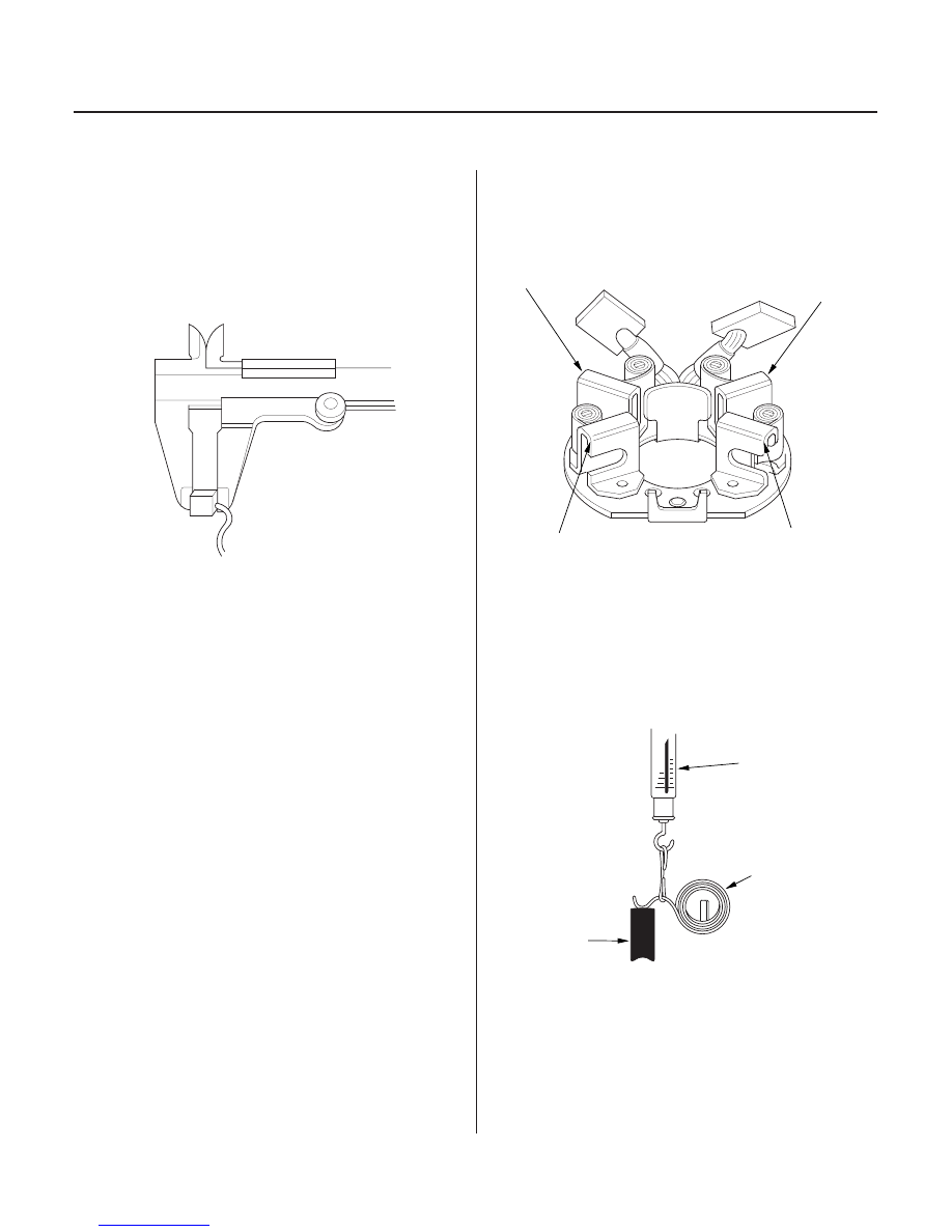
Starter Brush Inspection

Brush Length
Standard (New): 15.8

16.2 mm (0.62

0.64 in.)

Service Limit:

11.0 mm (0.43 in.)

Starter Brush Holder Test

Spring Tension:
15.7

17.7 N (1.6

1.8 kgf, 3.53

3.97 lbf)

4-12

Starting System

Starter Overhaul (cont’d)

B

A

A

B

B

C

A

11. Measure the brush length. If it is not within the

service limit, replace the brush holder assembly.

12. Check that there is no continuity between the (

)

brush holder (A) and (

) brush holder (B). If there

is continuity, replace the brush holder assembly.

13. Insert the brush (A) into the brush holder, and bring

the brush into contact with the commutator, then
attach a spring scale (B) to the spring (C). Measure
the spring tension at the moment the spring lifts off
the brush.

03/07/29 09:07:21 61S0X050_040_0012

*11

*12

*13

*14

Overrunning Clutch Inspection

4-13

B

A

A

B

14. Pry back each brush spring with a screwdriver, then

position the brush about halfway out of its holder,
and release the spring to hold it there.

15. Install the armature in the housing. Next, pry back

each brush spring again, and push the brush down
until it seats against the commutator, then release
the spring against the end of the brush.

NOTE: To seat new brushes, slip a strip of

500 or

600 sandpaper, with the grit side up, between the

commutator and each brush, and smoothly rotate
the armature. The contact surface of the brushes
will be sanded to the same contour as the
commutator.

16. Install the starter end cover (A) to retain the brush

holder (B).

17. Slide the overrunning clutch along the shaft.

Replace it if it does not slide smoothly.

18. Rotate the overrunning clutch (A) both ways. If it

does not lock in either direction or it locks in both
directions, replace it.

19. If the starter drive gear (B) is worn or damaged,

replace the overrunning clutch assembly; the gear
is not available separately.

Check the condition of the torque converter ring
gear if the starter drive gear teeth are damaged.

20. Reassemble the starter in reverse order of

disassembly.

03/07/29 09:07:22 61S0X050_040_0013

01

S0X4A00A26100000000DAAT00

4-14

Ignition System

Component Location Index

IGNITION COIL

SPARK PLUG

Replacement, page 4-17

Inspection, page 4-18

03/07/29 09:07:23 61S0X050_040_0014

*01

S0X4A00A26100000000EAAT00

4-15

Circuit Diagram

No.7 (15A)

: 2001 2004 models

: 1999 2000 models

No.11 (15A)

PCM

: Ignition Control Module

ICM

G101

No.5

BLK/RED

BLK/YEL

ICM

BLK

BLK

ICM

BLK/YEL

WHT/BLU

No.6

No.4

YEL

BLK/YEL

ICM

BLK

No.3

BLK

ICM

BLK/YEL

BLU

RED

BLK/YEL

ICM

BLK

No.2

No.1

BLK

ICM

BLK/YEL

YEL/GRN

BLK/YEL

*

BLK/YEL

IG1

BAT

IGNITION SWITCH

No.41 (120A)

UNDER HOOD FUSE/RELAY BOX

BATTERY

WHT

No.42 (50A)

IG1 HOT in ON (II)
and START (III)

DRIVER’S
UNDER DASH
FUSE/RELAY
BOX

IGNITION
COILS

SPARK
PLUGS

*

03/07/29 09:07:23 61S0X050_040_0015


Content   ..  21  22  23  24   ..