Honda Element. Manual - part 792


  Index      Honda     Honda Element - service repair manual 2007-2008 year


Search            


Content   ..  790  791  792  793   ..


Honda Element. Manual - part 792


8. Clear the DTC with the HDS.  

9. Turn the ignition switch OFF, then disconnect the HDS.  

10. Test-drive the vehicle at 19 mph (30 km/h) or more.  

11. Check for DTCs with the HDS. 

Is DTC 12, 14, 16, or 18 indicated?  

YES -Check for loose terminals in the VSA modulator-control unit 47P connector. If necessary, 
substitute a known-good VSA modulator-control unit (see VSA MODULATOR-CONTROL UNIT 
REMOVAL AND INSTALLATION
 ), and retest. 

NO -Replace the original wheel sensor (see WHEEL SENSOR REPLACEMENT ). 

DTC 21,22,23,24: MAGNETIC ENCODER 

1. Turn the ignition switch ON (II).  

2. Clear the DTC with the HDS.  

3. Turn the ignition switch OFF, then disconnect the HDS.  

4. Test-drive the vehicle at 19 mph (30 km/h) or more.  

5. Check for DTCs with the HDS. 

Is DTC 21,22,23, or 24 indicated?  

YES -Go to step 6. 

NO -The system is OK at this time. 

6. Check the appropriate magnetic encoder (see table) (see WHEEL SENSOR REPLACEMENT ). 

CONTINUITY SPECIFICATIONS 

Is the sensor OK?  

YES -Check for loose terminals in the VSA modulator-control unit 47P connector. If necessary, 
substitute a known-good VSA modulator-control unit (see VSA MODULATOR-CONTROL UNIT 
REMOVAL AND INSTALLATION
 ), and retest. 

NO -Replace the magnetic encoder. 

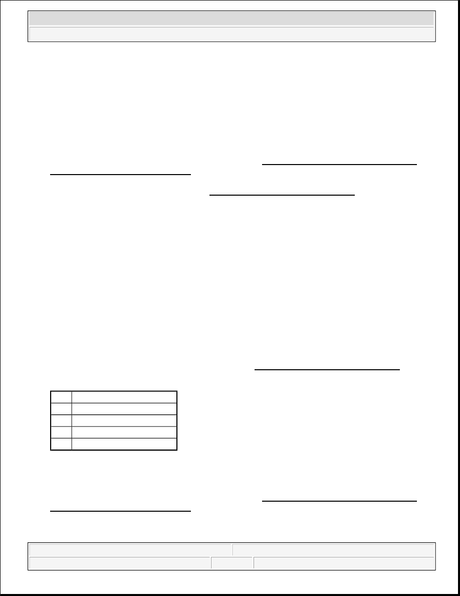
DTC Appropriate Wheel Sensor

21

Right-front

22

Left-front

23

Right-rear

24

Left-rear


2007 Honda Element EX 

2007-2008 BRAKES VSA (Vehicle Stability Assist) System Components - Element


DTC 25: YAW RATE SENSOR; DTC 26: LATERAL ACCELERATION SENSOR; DTC 28: 
LONGITUDINAL ACCELERATION SENSOR; DTC 104: SENSOR CLUSTER 

1. Check the size, air pressure, and the amount of wear of all four tires, and check the wheel alignment (see 

WHEEL ALIGNMENT ). 

Is the tire condition and wheel alignment OK?  

YES -Go to step 2. 

NO -Make sure the suspension is not modified, and adjust the wheel alignment correctly, and recheck by 
test-driving. 

2. Turn the ignition switch OFF.  

3. Disconnect the sensor cluster 6P connector.  

4. Disconnect the VSA modulator-control unit 47P connector.  

5. Turn the ignition switch ON (II).  

6. Measure the voltage between body ground and VSA modulator-control unit 47P connector terminals No. 

6, No. 25, No. 29, and No. 31 individually. 

Fig. 32: Measuring Voltage Between Body Ground And VSA Modulator-Control Unit 47P 
Connector Terminals
 
Courtesy of AMERICAN HONDA MOTOR CO., INC. 

Is there 0.1 V or more?  

YES -Repair short to power in the wire between the VSA modulator-control unit and the sensor cluster. 

NO -Go to step 7. 

7. Turn the ignition switch OFF.  

8. Check for continuity between body ground and VSA modulator-control unit 47P connector terminals No. 

6, No. 25, No. 29, and No. 31 individually. 


2007 Honda Element EX 

2007-2008 BRAKES VSA (Vehicle Stability Assist) System Components - Element


Fig. 33: Checking Continuity Between Body Ground And VSA Modulator-Control Unit 47P 
Connector Terminals
 
Courtesy of AMERICAN HONDA MOTOR CO., INC. 

Is there continuity?  

YES -Repair short to body ground in the wire between the VSA modulator-control unit and the sensor 
cluster. 

NO -Go to step 9. 

9. Check for continuity between VSA modulator-control unit 47P connector terminals No. 6, No. 25, No. 

29, and No. 31 and sensor cluster 6P connector terminals No. 1, No. 3, No. 2, and No. 5. 

Fig. 34: Checking Continuity Between VSA Modulator-Control Unit 47P Connector Terminals 
Courtesy of AMERICAN HONDA MOTOR CO., INC.


2007 Honda Element EX 

2007-2008 BRAKES VSA (Vehicle Stability Assist) System Components - Element


Is there continuity?  

YES -Go to step 10. 

NO -Repair open in the wire between the VSA modulator-control unit and the sensor cluster. 

10. Substitute a known-good sensor cluster (see SENSOR CLUSTER REPLACEMENT ). 

11. Reconnect all of the disconnected connectors.  

12. Turn the ignition switch ON (II).  

13. Clear the DTC with the HDS.  

14. Do the VSA sensor neutral position memorization (see VSA SENSOR NEUTRAL POSITION 

MEMORIZATION ).  

15. Turn the ignition switch OFF, then disconnect the HDS.  

16. Test-drive the vehicle around a number of corners.  

17. Check for DTCs with the HDS. 

Is DTC 25,26,28, or 104 indicated?  

YES -Check for loose terminals in the VSA modulator-control unit 47P connector. If necessary, 
substitute a known-good VSA modulator-control unit (see VSA MODULATOR-CONTROL UNIT 
REMOVAL AND INSTALLATION
 ), and retest. 

NO -Replace the sensor cluster (see SENSOR CLUSTER REPLACEMENT ). 

DTC 27: STEERING ANGLE SENSOR 

1. Check the size, air pressure, and amount of wear of all four tires, and check the wheel alignment (see 

WHEEL ALIGNMENT ). 

Is the tire condition and wheel alignment OK?  

YES -Go to step 2. 

NO -Make sure the suspension is not modified, and adjust the wheel alignment correctly, and recheck by 
test-driving. 

2. Turn the ignition switch ON (II).  

3. Clear the DTC with the HDS.  

4. Turn the ignition switch OFF, then disconnect the HDS.  

5. Test-drive the vehicle around a number of corners. 

NOTE:

Check that the sensor cluster mounting bracket is not bent or twisted, and 
make sure the sensor cluster is mounted properly and fixed.


2007 Honda Element EX 

2007-2008 BRAKES VSA (Vehicle Stability Assist) System Components - Element


Content   ..  790  791  792  793   ..