Honda Element. Manual - part 791


  Index      Honda     Honda Element - service repair manual 2007-2008 year


Search            


Content   ..  789  790  791  792   ..


Honda Element. Manual - part 791


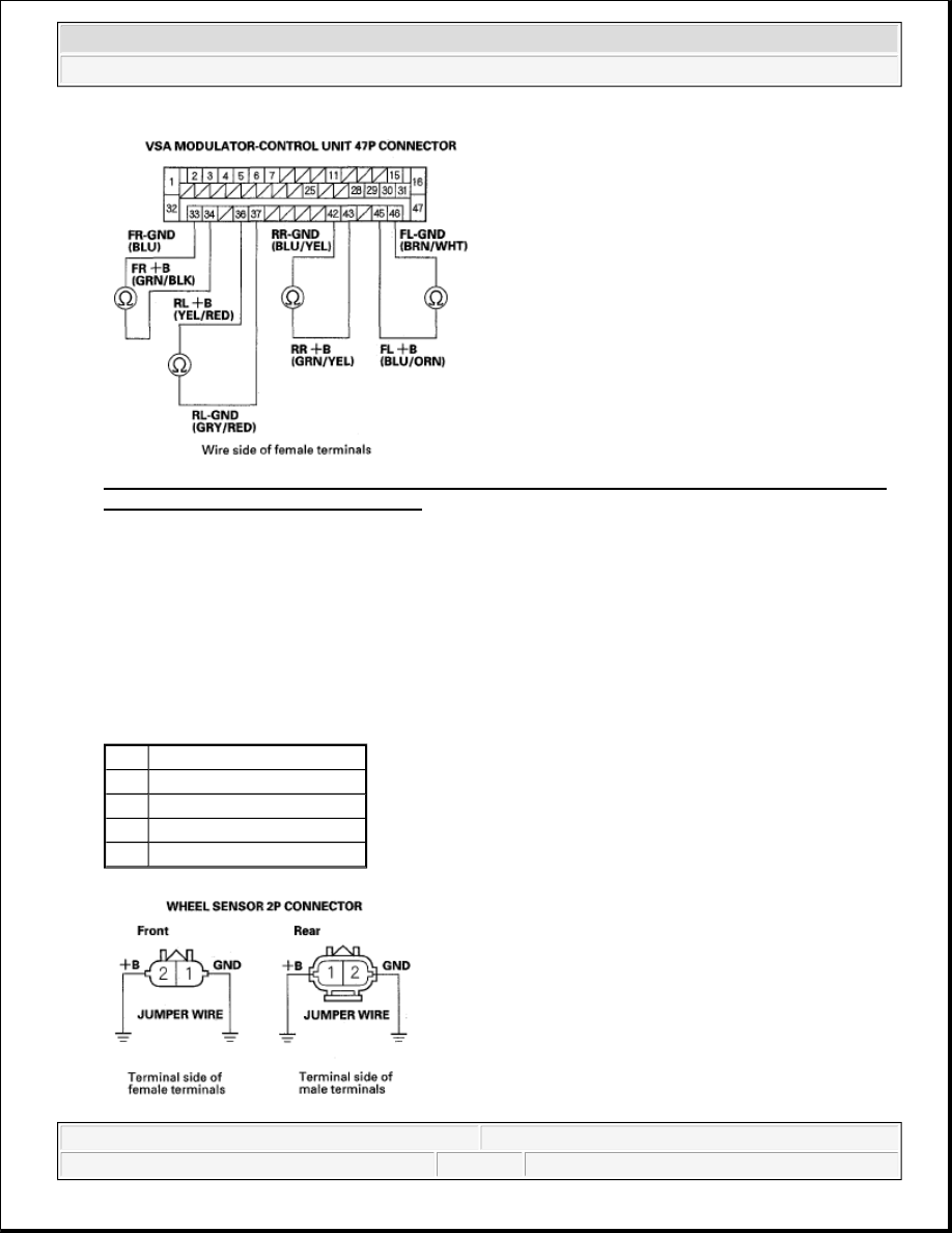
Fig. 27: Checking Continuity Between Appropriate Wheel Sensor +B And Gnd Terminals Of VSA 
Modulator-Control Unit 47P Connector
 
Courtesy of AMERICAN HONDA MOTOR CO., INC. 

Is there continuity?  

YES -Repair short in the wires between the VSA modulator-control unit and the wheel sensor. 

NO -Go to step 11. 

11. Connect wheel sensor 2P connector terminals No. 1 and No. 2 to body ground with a jumper wire. 

CONTINUITY SPECIFICATIONS 

DTC Appropriate Wheel Sensor

11

Right-front

13

Left-front

15

Right-rear

17

Left-rear


2007 Honda Element EX 

2007-2008 BRAKES VSA (Vehicle Stability Assist) System Components - Element


Fig. 28: Connecting Wheel Sensor 2P Connector Terminals No. 1 And 2 To Body Ground With 
Jumper Wire
 
Courtesy of AMERICAN HONDA MOTOR CO., INC. 

12. Check for continuity between body ground and the appropriate wheel sensor +B and GND terminals of 

the VSA modulator-control unit 47P connector individually (see table). 

CONTINUITY SPECIFICATIONS 

Fig. 29: Checking Continuity Between Body Ground And Appropriate Wheel Sensor +B And Gnd 
Terminals Of VSA Modulator-Control Unit
 
Courtesy of AMERICAN HONDA MOTOR CO., INC. 

Is there continuity?  

YES -Go to step 13. 

NO -Repair open in the wire between the VSA modulator-control unit and the wheel sensor. 

13. On the sensor side, measure the resistance between the appropriate wheel sensor 2P connector terminals, 

then re-measure the resistance between the same terminals after reversing the positive tester probe and 
negative tester probe. 

RESISTANCE SPECIFICATIONS 

DTC

Appropriate Terminal

+B

GND

11 (Right-front) FR+B: No. 34 FR-GND: No. 33
13 (Left-front)

FL+B: No. 45 FL-GND: No. 46

15 (Right-rear) RR+B: No. 43 RR-GND: No. 42
17 (Left-rear)

RL +B: No. 36 RL-GND: No. 37

DTC Appropriate Wheel Sensor


2007 Honda Element EX 

2007-2008 BRAKES VSA (Vehicle Stability Assist) System Components - Element


Fig. 30: Measuring Resistance Between Appropriate Wheel Sensor 2P Connector Terminals 
Courtesy of AMERICAN HONDA MOTOR CO., INC. 

Is the resistance infinity (open circuit) or has continuity in both directions?  

YES -Replace the wheel sensor (see WHEEL SENSOR REPLACEMENT ). 

NO -Check for loose terminals in the VSA modulator-control unit 47P connector. If necessary, substitute 
a known-good VSA modulator-control unit (see VSA MODULATOR-CONTROL UNIT REMOVAL 
AND INSTALLATION
 ), and retest. 

DTC 12,14,16,18: WHEEL SENSOR (ELECTRICAL NOISE/INTERMITTENT INTERRUPTION) 

1. Turn the ignition switch OFF.  

2. Check the appropriate wheel sensor and magnetic encoder (see WHEEL SENSOR REPLACEMENT ). 

RESISTANCE SPECIFICATIONS 

Are they OK?  

YES -Go to step 3. 

11

Right-front

13

Left-front

15

Right-rear

17

Left-rear

NOTE:

If the ABS and VSA indicators come on because of electrical noise, the 
indicator goes off when you test-drive the vehicle at 19 mph (30 km/h).

DTC Appropriate Wheel Sensor

12

Right-front

14

Left-front

16

Right-rear

18

Left-rear


2007 Honda Element EX 

2007-2008 BRAKES VSA (Vehicle Stability Assist) System Components - Element


NO -Reinstall or replace the appropriate wheel sensor or magnetic encoder. 

3. Disconnect the VSA modulator-control unit 47P connector.  

4. Check for continuity between the appropriate wheel sensor GND terminal and other wheel sensor GND 

terminals of the VSA modulator-control unit 47P connector (see table). 

CONTINUITY SPECIFICATIONS 

Fig. 31: Checking Continuity Between Appropriate Wheel Sensor Gnd Terminal And Other Wheel 
Sensor GND Terminals
 
Courtesy of AMERICAN HONDA MOTOR CO., INC. 

Is there continuity?  

YES -Repair short in the wires between the appropriate wheel sensor and the other wheel sensor. 

NO -Go to step 5. 

5. Substitute a known-good wheel sensor for the appropriate wheel sensor (see table). 

CONTINUITY SPECIFICATIONS 

6. Reconnect all of the disconnected connectors.  

7. Turn the ignition switch ON (II).  

DTC Appropriate Terminal Other Terminals

12

FR-GND: No. 33

No. 46 No. 42 No. 37

14

FL-GND: No. 46

No. 33 No. 42 No. 37

16

RR-GND: No. 42

No. 33 No. 46 No. 37

18

RL-GND: No. 37

No. 33 No. 46 No. 42

DTC Appropriate Wheel Sensor

12

Right-front

14

Left-front

16

Right-rear

18

Left-rear


2007 Honda Element EX 

2007-2008 BRAKES VSA (Vehicle Stability Assist) System Components - Element


Content   ..  789  790  791  792   ..