Honda Element. Manual - part 790


  Index      Honda     Honda Element - service repair manual 2007-2008 year


Search            


Content   ..  788  789  790  791   ..


Honda Element. Manual - part 790


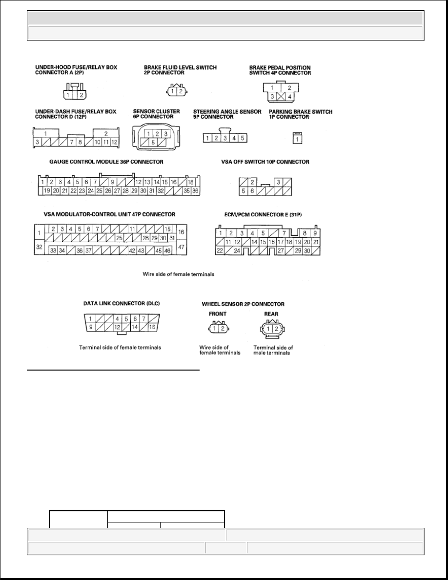
Fig. 23: VSA System Circuit Diagram (3 Of 3) 
Courtesy of AMERICAN HONDA MOTOR CO., INC. 

DTC TROUBLESHOOTING 

DTC 11,13,15,17: WHEEL SENSOR (SHORT TO POWER/SHORT TO BODY GROUND/OPEN) 

1. Turn the ignition switch OFF.  

2. Disconnect the VSA modulator-control unit 47P connector.  

3. Start the engine.  

4. Measure the voltage between body ground and the appropriate wheel sensor +B and GND terminals of 

the VSA modulator-control unit 47P connector individually (see table). 

DTC TROUBLESHOOTING 

DTC

Appropriate Terminal


2007 Honda Element EX 

2007-2008 BRAKES VSA (Vehicle Stability Assist) System Components - Element


Fig. 24: Measuring Voltage Between Body Ground And Appropriate Wheel Sensor +B And GND 
Terminals
 
Courtesy of AMERICAN HONDA MOTOR CO., INC. 

Is there 0.1 V or more?  

YES -Repair short to power in the wire between the VSA modulator-control unit and the appropriate 
wheel sensor. 

NO -Go to step 5. 

5. Turn the ignition switch OFF.  

6. Check for continuity between body ground and the appropriate wheel sensor +B and GND terminals of 

the VSA modulator-control unit 47P connector individually (see table). 

CONTINUITY SPECIFICATIONS 

+B

GND

11 (Right-front) FR+B: No. 34 FR-GND: No. 33
13 (Left-front) FL+B: No. 45 FL-GND: No. 46
15 (Right-rear) RR+B: No. 43 RR-GND: No. 42
17 (Left-rear)

RL+B: No. 36 RL-GND: No. 37

DTC

Appropriate Terminal

+B

GND

11 (Right-front) FR+B: No. 34 FR-GND: No. 33
13 (Left-front)

FL +B: No. 45 FL-GND: No. 46

15 (Right-rear) RR-f-B: No. 43 RR-GND: No. 42
17 (Left-rear)

RL+B: No. 36 RL-GND: No. 37


2007 Honda Element EX 

2007-2008 BRAKES VSA (Vehicle Stability Assist) System Components - Element


Fig. 25: Checking Continuity Between Body Ground And Appropriate Wheel Sensor +B And Gnd 
Terminals
 
Courtesy of AMERICAN HONDA MOTOR CO., INC. 

Is there continuity?  

YES -Go to step 7. 

NO -Go to step 9. 

7. Disconnect the appropriate wheel sensor 2P connector.  

8. Check for continuity between body ground and the appropriate wheel sensor +B and GND terminals of 

the VSA modulator-control unit 47P connector individually (see table). 

CONTINUITY SPECIFICATIONS 

DTC

Appropriate Terminal

+B

GND

11 (Right-front) FR+B: No. 34 FR-GND: No. 33
13 (Left-front) FL+B: No. 45 FL-GND: No. 46
15 (Right-rear) RR+B: No. 43 RR-GND: No. 42
17 (Left-rear)

RL+B: No. 36 RL-GND: No. 37


2007 Honda Element EX 

2007-2008 BRAKES VSA (Vehicle Stability Assist) System Components - Element


Fig. 26: Checking Continuity Between Body Ground And Appropriate Wheel Sensor +B And Gnd 
Terminals
 
Courtesy of AMERICAN HONDA MOTOR CO., INC. 

Is there continuity?  

YES -Repair short to body ground in the wire between the VSA modulator-control unit and the wheel 
sensor. 

NO -Replace the wheel sensor (see WHEEL SENSOR REPLACEMENT ). 

9. Disconnect the appropriate wheel sensor 2P connector.  

10. Check for continuity between the appropriate wheel sensor +B and GND terminals of the VSA 

modulator-control unit 47P connector (see table). 

CONTINUITY SPECIFICATIONS 

DTC

Appropriate Terminal

+B

GND

11 (Right-front) FR+B: No. 34 FR-GND: No. 33
13 (Left-front) FL +B: No. 45 FL-GND: No. 46
15 (Right-rear) RR+B: No. 43 RR-GND: No. 42
17 (Left-rear)

RL+B: No. 36 RL-GND: No. 37


2007 Honda Element EX 

2007-2008 BRAKES VSA (Vehicle Stability Assist) System Components - Element


Content   ..  788  789  790  791   ..