Honda Element. Manual - part 786
sensor (short to
power/short to
body ground/open)
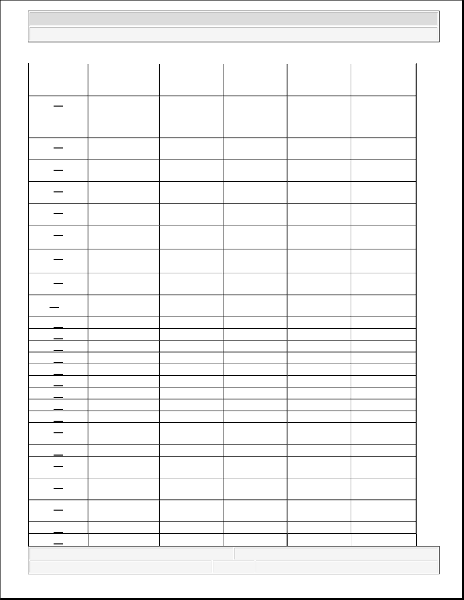
18
Left-rear wheel
sensor (electrical
noise/intermittent
interruption)
ON
ON or OFF
(1)
ON
ON
21
Right-front
magnetic encoder
ON
ON or OFF
(1)
ON
ON
22
Left-front
magnetic encoder
ON
ON or OFF
(1)
ON
ON
23
Right-rear
magnetic encoder
ON
ON or OFF
(1)
ON
ON
24
Left-rear magnetic
encoder
ON
ON or OFF
(1)
ON
ON
25
Yaw rate sensor
OFF/ON or OFF
(2)
OFF
ON
ON
26
Lateral
acceleration sensor
OFF/ON or OFF
(2)
OFF
ON
ON
27
Steering angle
sensor
OFF
OFF
ON
ON
28
(2)
Longitudinal
acceleration sensor
ON
OFF
ON
ON
31
ABS solenoid
ON
ON
ON
ON
32
ABS solenoid
ON
ON
ON
ON
33
ABS solenoid
ON
ON
ON
ON
34
ABS solenoid
ON
ON
ON
ON
35
ABS solenoid
ON
ON
ON
ON
36
ABS solenoid
ON
ON
ON
ON
37
ABS solenoid
ON
ON
ON
ON
38
ABS solenoid
ON
ON
ON
ON
51
Motor lock
ON
OFF
ON
ON
52
Motor stuck
ON/OFF
ON
OFF
ON
ON
54
Fail-safe relay
ON
ON
ON
ON
61
Low +B-FSR
voltage
ON
ON or OFF
ON
ON
62
High +B-FSR
voltage
ON
ON
ON
ON
64
Sensor power
voltage
OFF/ON
(2)
OFF
ON
ON
65
Brake fluid level
OFF
OFF
ON
ON
66
VSA pressure
OFF
OFF
ON
ON
2007 Honda Element EX
2007-2008 BRAKES VSA (Vehicle Stability Assist) System Components - Element