Honda Element. Manual - part 775
SYSTEM DESCRIPTION
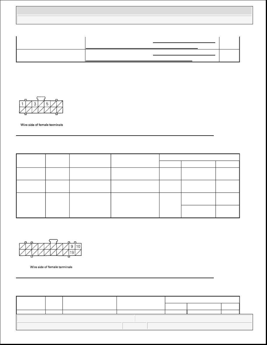
TPMS CONTROL UNIT INPUTS AND OUTPUTS FOR CONNECTOR A (14P)
Fig. 11: Identifying TPMS Control Unit Inputs And Outputs Connector Terminals (14P)
Courtesy of AMERICAN HONDA MOTOR CO., INC.
VOLTAGE SPECIFICATION
TPMS CONTROL UNIT INPUTS AND OUTPUTS FOR CONNECTOR B (20P)
Fig. 12: Identifying TPMS Control Unit Inputs And Outputs Connector Terminals (20P)
Courtesy of AMERICAN HONDA MOTOR CO., INC.
VOLTAGE SPECIFICATION
TPMS indicator does not come
on, and no DTCs are stored
Symptom Troubleshooting (see TPMS INDICATOR DOES
NOT COME ON, AND NO DTCS ARE STORED )
TPMS indicator does not go
off, and no DTCs are stored
Symptom Troubleshooting (see TPMS INDICATOR DOES
NOT GO OFF, AND NO DTCS ARE STORED )
Terminal
number
Wire
color
Terminal sign
(Terminal name)
Description
Signal
Terminal
Conditions
Voltage
1
RED/BLU
+B (Battery
positive)
Power source for the
TPMS control unit
1-GND At all times
Battery
voltage
3
BLK
GND (Ground)
Ground for the TPMS
control unit
3-GND At all times
Less than
0.1V
5
YEL
IG1 (Ignition 1)
Power source for
activating the system
5-GND
Ignition switch
ON (II)
Battery
voltage
Ignition switch
OFF
Less than
0.1V
Terminal
number
Wire
color
Terminal sign
(Terminal name)
Description
Signal
Terminal
Conditions
Voltage
2007 Honda Element EX
2007-2008 SUSPENSION TPMS (Tire Pressure Monitoring System) - Element