Honda Element. Manual - part 707


  Index      Honda     Honda Element - service repair manual 2007-2008 year


Search            


Content   ..  705  706  707  708   ..


Honda Element. Manual - part 707


2007-08 ACCESSORIES AND EQUIPMENT

Power Mirrors - Element 

COMPONENT LOCATION INDEX 

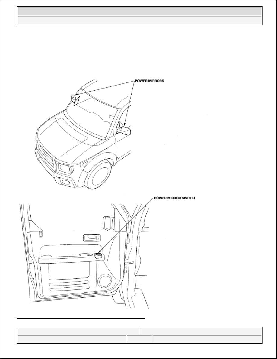
Fig. 1: Identifying Power Mirror Components Location 
Courtesy of AMERICAN HONDA MOTOR CO., INC.


2007 Honda Element EX 

2007-08 ACCESSORIES AND EQUIPMENT Power Mirrors - Element


2007 Honda Element EX 

2007-08 ACCESSORIES AND EQUIPMENT Power Mirrors - Element


CIRCUIT DIAGRAM 

Fig. 2: Power Mirror Circuit Diagram 
Courtesy of AMERICAN HONDA MOTOR CO., INC. 

FUNCTION TEST 


2007 Honda Element EX 

2007-08 ACCESSORIES AND EQUIPMENT Power Mirrors - Element


1. Remove the driver's door panel (see FRONT DOOR PANEL REMOVAL/INSTALLATION ).  

2. Disconnect the 13P connector (A) from the power mirror switch (B). 

Fig. 3: Identifying Power Mirror Switch 13P Connector Terminals 
Courtesy of AMERICAN HONDA MOTOR CO., INC. 

3. Choose the appropriate test based on the symptom: 

Both mirrors don't work, go to step 4.  

Left mirror doesn't work, go to step 6.  

Right mirror doesn't work, go to step 7.  

Both mirrors  

4. Measure voltage between the No. 2 terminal and body ground with the ignition switch ON (II). There 

should be battery voltage. 

If there is no battery voltage, check for: 

Blown No. 14 (10 A) fuse in the under-dash fuse/relay box.  

An open in the BLK/YEL wire.  

If there is battery voltage, go to step 5.  

5. Check for continuity between the No. 6 terminal and body ground. 

There should be continuity. 

If there is no continuity, check for: 

An open in the BLK wire.  

Poor ground (G501).  

If there is continuity, check both mirrors individually as described in step 6 and step 7.  

Left mirror  


2007 Honda Element EX 

2007-08 ACCESSORIES AND EQUIPMENT Power Mirrors - Element


6. Connect the No. 2 terminal to the No. 10 terminal, and the No. 5 (then No. 12) terminal to No. 6 terminal 

with jumper wires. The left mirror should tilt down (then swing left) with the ignition switch ON (II). 

If the mirror does not tilt down (or does not swing left), check for an open in the GRN/WHT (or 
BLU/WHT) wire between the left mirror and the 13P connector. If the wire is OK, check the left 
mirror actuator (see POWER MIRROR ACTUATOR TEST ).  

If the mirror neither tilts down nor swings left, repair the BLU/BLK wire.  

If the mirror works properly, check the mirror switch (see POWER MIRROR ACTUATOR 
TEST
 ).  

Right mirror  

7. Connect the No. 2 terminal to the No. 11 terminal, and the No. 5 (then No. 13) terminal to No. 6 terminal 

with jumper wires. The right mirror should tilt down (then swing left) with the ignition switch ON (II). 

If the mirror does not tilt down (or does not swing left), check for an open in the GRN/WHT (or 
WHT/RED) wire between the right mirror and the 13P connector. If the wire is OK, check the right 
mirror actuator (see POWER MIRROR ACTUATOR TEST ).  

If the mirror neither tilts down nor swings left, repair the RED/YEL wire.  

If the mirror works properly, check the mirror switch (see POWER MIRROR ACTUATOR 
TEST
 ).  

POWER MIRROR SWITCH TEST/REPLACEMENT 

1. Remove the driver's door panel (see FRONT DOOR PANEL REMOVAL/INSTALLATION ).  

2. Disconnect the 13P connector from the power mirror switch (A). 

Fig. 4: Identifying Power Mirror Switch 13P Connector Terminals 
Courtesy of AMERICAN HONDA MOTOR CO., INC. 

3. Check for continuity between the terminals in each switch position according to Fig. 5


2007 Honda Element EX 

2007-08 ACCESSORIES AND EQUIPMENT Power Mirrors - Element


Content   ..  705  706  707  708   ..