Honda Element. Manual - part 698


  Index      Honda     Honda Element - service repair manual 2007-2008 year


Search            


Content   ..  696  697  698  699   ..


Honda Element. Manual - part 698


NO -Go to step 11. 

11. Turn the ignition switch OFF.  

12. Turn the ignition switch ON (II), and watch the immobilizer indicator. 

Does the immobilizer indicator stay on or flash?  

YES -Go to the immobilizer system's troubleshooting (see TROUBLESHOOTING ). 

NO -Go to step 13. 

13. Do the gauge self-diagnostic function without the HDS (see SELF-DIAGNOSTIC FUNCTION ). 

Are any indicators flashing?  

YES -Go to step 14. 

NO -Troubleshoot the gauge control module (see SELF-DIAGNOSTIC FUNCTION ). 

14. Turn the ignition switch OFF.  

15. Disconnect the HDS from the DLC.  

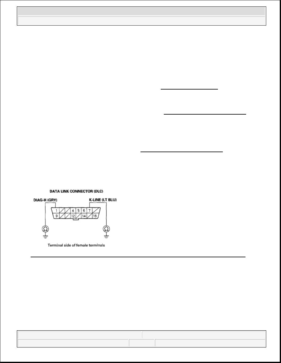
16. Check for continuity between body ground and DLC terminals No. 1 and No. 7 individually. 

Fig. 139: Checking Continuity Between Body Ground And DLC Terminals No. 1 And No. 7 
Courtesy of AMERICAN HONDA MOTOR CO., INC. 

Is there continuity?  

YES -Go to step 17. 

NO -Go to step 18. 

17. Continue to check for continuity between DLC terminals No. 1 and No. 7 and body ground individually, 

while disconnecting these parts, one at a time: 

Gauge control module 36P connector 


2007 Honda Element EX 

2007-2008 ENGINE PERFORMANCE PGM-FI System - Element


SRS unit connector A (28P)  

VSA modulator-control unit 47P connector  

Immobilizer control unit 7P connector  

TPMS control unit connector B (20P) 

Fig. 140: Checking Continuity Between DLC Terminals No. 1 And No. 7 And Body Ground 
Courtesy of AMERICAN HONDA MOTOR CO., INC. 

Does continuity go away when one of the above components is disconnected?  

YES -Replace the part that caused an open when it was disconnected. 

NO -Repair short in the wire between the DLC No. 7 (K-line) and the VSA modulator-control unit, the 
SRS unit, the TPMS control unit, or the gauge control module, or DLC No. 1 (DIAG-H line) and the 
immobilizer control unit. 

18. Connect DLC terminals No. 1 and No. 7 to body ground with a jumper wire. 

Fig. 141: Connecting DLC Terminals No. 1 And No. 7 To Body Ground With Jumper Wire 
Courtesy of AMERICAN HONDA MOTOR CO., INC. 

19. Check for continuity between body ground and these connector terminals: 

CONNECTOR TERMINAL SPECIFICATION 

Connector

Unit Terminal DLC Terminal


2007 Honda Element EX 

2007-2008 ENGINE PERFORMANCE PGM-FI System - Element


Is there continuity between the DLC terminal and each of the terminals in the chart?  

YES -Replace the unit that does not communicate with the HDS. 

NO -Repair open in the wire between the DLC (K-line or DIAG-H line) and the appropriate connector. 

20. Do the gauge self-diagnostic function (see SELF-DIAGNOSTIC FUNCTION ).  

21. Check odometer/trip meter for "Error 1" message. 

Is Error 1 displayed?  

YES -Go to step 35. 

NO -Go to step 22. 

22. Turn the ignition switch OFF.  

23. Disconnect the HDS from the DLC.  

24. Measure voltage between DLC terminal No. 16 and body ground. 

Fig. 142: Measuring Voltage Between DLC Terminal No. 16 And Body Ground 
Courtesy of AMERICAN HONDA MOTOR CO., INC. 

Is there battery voltage?  

YES -Go to step 25. 

NO -Repair open in the wire between DLC terminal No. 16 and the No. 9 BACK UP (10 A) fuse in the 
under-hood fuse/relay box. 

Gauge control module 36P

No. 9 (LT BLU) No. 7 (LT BLU)

VSA modulator-control unit 47P No. 2 (LT BLU) No. 7 (LT BLU)
SRS unit A 28P

No. 24 (LT BLU) No. 7 (LT BLU)

TPMS control unit B 20P

No. 9 (LT BLU) No. 7 (LT BLU)

Immobilizer control unit 7P

No. 3 (GRY)

No. 1 (GRY)


2007 Honda Element EX 

2007-2008 ENGINE PERFORMANCE PGM-FI System - Element


25. Measure voltage between DLC terminals No. 4 and No. 16. 

Fig. 143: Measuring Voltage Between DLC Terminals No. 4 And No. 16 
Courtesy of AMERICAN HONDA MOTOR CO., INC. 

Is there battery voltage?  

YES -Go to step 26. 

NO -Repair open in the wire between DLC terminal No. 4 and G451. 

26. Connect the HDS to the DLC (see GENERAL TROUBLESHOOTING INFORMATION ).  

27. Jump the SCS line with the HDS.  

28. Disconnect ECM/PCM connector E (31P).  

29. Disconnect the HDS from the DLC.  

30. Connect DLC terminal No. 6 to body ground with a jumper wire. 

Fig. 144: Connecting DLC Terminal No. 6 To Body Ground With Jumper Wire 
Courtesy of AMERICAN HONDA MOTOR CO., INC. 

31. Check for continuity between ECM/PCM connector terminal E11 and body ground. 


2007 Honda Element EX 

2007-2008 ENGINE PERFORMANCE PGM-FI System - Element


Content   ..  696  697  698  699   ..