Honda Element. Manual - part 664


  Index      Honda     Honda Element - service repair manual 2007-2008 year


Search            


Content   ..  662  663  664  665   ..


Honda Element. Manual - part 664


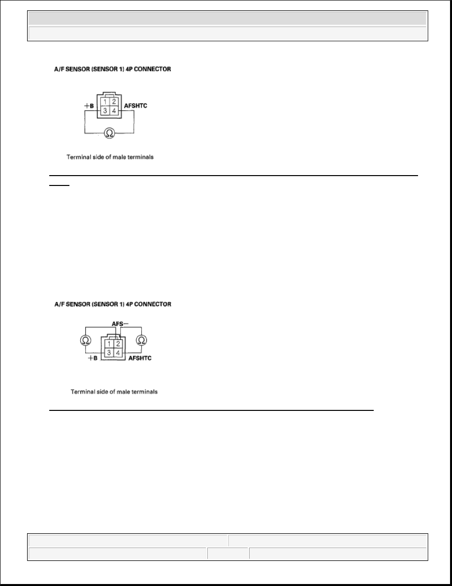
Fig. 32: Measuring Resistance Between A/F Sensor (Sensor 1) 4P Connector Terminals No. 3 And 
No. 4
 
Courtesy of AMERICAN HONDA MOTOR CO., INC. 

Is there 2.1-2.9 ohms at room temperature?  

YES -Go to step 9. 

NO -Go to step 23. 

9. At the sensor side, check for continuity between A/F sensor (Sensor 1) 4P connector terminals No. 2 and 

No. 3, and No. 2 and No. 4 individually. 

Fig. 33: Checking Continuity Between A/F Sensor (Sensor 1) 4P Connector Terminals 
Courtesy of AMERICAN HONDA MOTOR CO., INC. 

Is there continuity?  

YES -Go to step 23. 

NO -Go to step 10. 

10. Jump the SCS line with the HDS.  

11. Disconnect ECM/PCM connector A (31P).  

12. Check for continuity between ECM/PCM connector terminal A10 and body ground. 


2007 Honda Element EX 

2007-2008 ENGINE PERFORMANCE PGM-FI System - Element


Fig. 34: Checking Continuity Between ECM/PCM Connector Terminal A10 And Body Ground 
Courtesy of AMERICAN HONDA MOTOR CO., INC. 

Is there continuity?  

YES -Repair short in the wire between the ECM/PCM (A10) and the A/F sensor (Sensor 1), then go to 
step 24. 

NO -Go to step 13. 

13. Connect A/F sensor (Sensor 1) 4P connector terminal No. 4 to body ground with a jumper wire. 

Fig. 35: Connecting A/F Sensor (Sensor 1) 4P Connector Terminal No. 4 To Body Ground With 
Jumper Wire
 
Courtesy of AMERICAN HONDA MOTOR CO., INC. 

14. Check for continuity between ECM/PCM connector terminal A10 and body ground. 


2007 Honda Element EX 

2007-2008 ENGINE PERFORMANCE PGM-FI System - Element


Fig. 36: Checking Continuity Between ECM/PCM Connector Terminal A10 And Body Ground 
Courtesy of AMERICAN HONDA MOTOR CO., INC. 

Is there continuity?  

YES -Go to step 15. 

NO -Repair open in the wire between the ECM/PCM (A10) and the A/F sensor (Sensor 1), then go to step 
24. 

15. Remove the glove box (see GLOVE BOX REMOVAL/INSTALLATION ).  

16. Remove the A/F sensor relay (LAF) (A). 

Fig. 37: Identifying A/F Sensor Relay (LAF) 
Courtesy of AMERICAN HONDA MOTOR CO., INC. 

17. Connect A/F sensor (Sensor 1) 4P connector terminal No. 3 to body ground with a jumper wire. 


2007 Honda Element EX 

2007-2008 ENGINE PERFORMANCE PGM-FI System - Element


Fig. 38: Connecting A/F Sensor (Sensor 1) 4P Connector Terminal No. 3 To Body Ground With 
Jumper Wire
 
Courtesy of AMERICAN HONDA MOTOR CO., INC. 

18. Check for continuity between A/F sensor relay (LAF) 4P connector terminal No. 1 and body ground. 

Fig. 39: Checking Continuity Between A/F Sensor Relay (LAF) 4P Connector Terminal No. 1 And 
Body Ground
 
Courtesy of AMERICAN HONDA MOTOR CO., INC. 

Is there continuity?  

YES -Go to step 19. 

NO -Repair open in the wire between the A/F sensor (Sensor 1) and the A/F sensor relay (LAF), then go 
to step 24. 

19. Disconnect ECM/PCM connector E (31P).  

20. Check for continuity between ECM/PCM connector terminal E8 and body ground. 


2007 Honda Element EX 

2007-2008 ENGINE PERFORMANCE PGM-FI System - Element


Content   ..  662  663  664  665   ..