Honda Element. Manual - part 652


  Index      Honda     Honda Element - service repair manual 2007-2008 year


Search            


Content   ..  650  651  652  653   ..


Honda Element. Manual - part 652


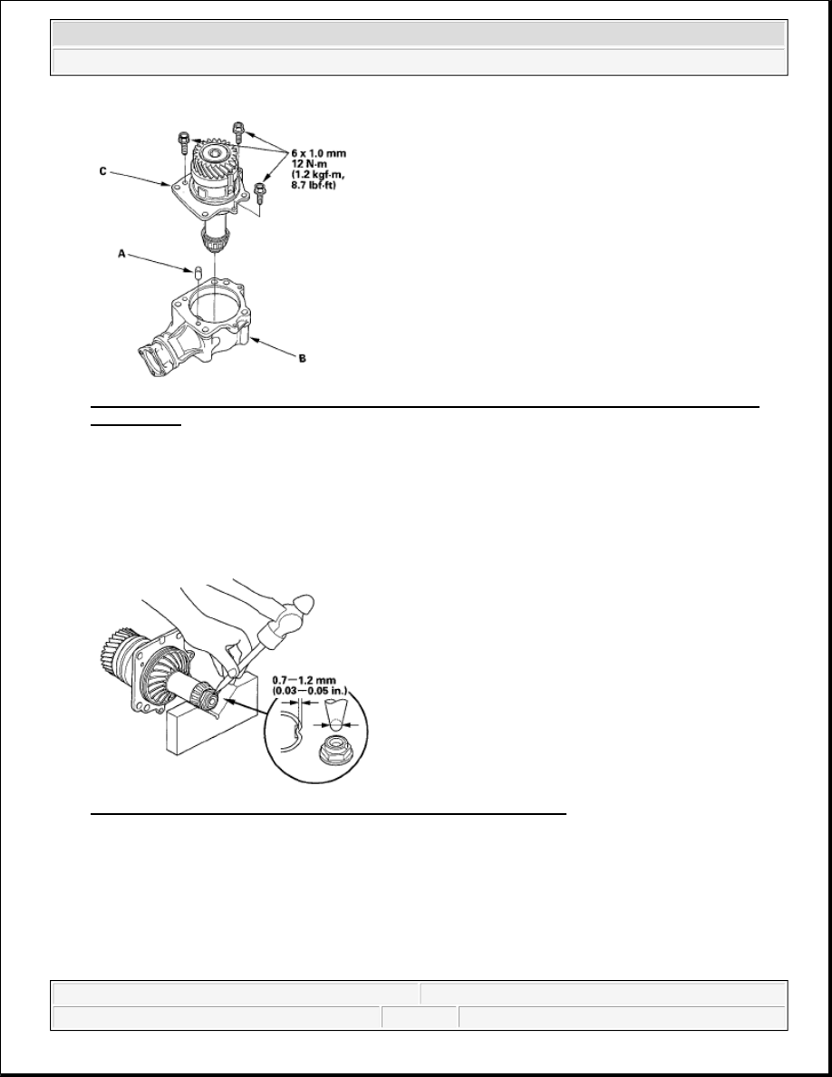
Fig. 229: Identifying Dowel Pin, Transfer Housing And Transfer Holder Assembly With Torque 
Specification
 
Courtesy of AMERICAN HONDA MOTOR CO., INC. 

44. Rotate the companion flange several times to seat the tapered roller bearings.  

45. Recheck and make sure the total starting torque is within the standard.  

46. Remove the transfer holder assembly from the transfer housing.  

47. Stake the locknut on the transfer shaft using a 3.5 mm punch. 

Fig. 230: Removing Transfer Holder Assembly Of Transfer Housing 
Courtesy of AMERICAN HONDA MOTOR CO., INC. 

48. Coat the new O-ring (A) with MTF, install it on the transfer holder assembly (B), then install the dowel 

pin (C) and transfer holder assembly in the transfer housing (D). 


2007 Honda Element EX 

2007-2008 TRANSMISSION Manual Transmission - Element


Fig. 231: Identifying O-Ring, MTF, Transfer Holder Assembly And Dowel Pin With Torque 
Specification
 
Courtesy of AMERICAN HONDA MOTOR CO., INC. 

SUPPLEMENTAL RESTRAINT SYSTEM (SRS) (If automatic transmission maintenance is required)  

The ELEMENT SRS includes a driver's airbag in the steering wheel hub, a passenger's airbag in the dashboard 
above the glove box, seat belt tensioners in the front seat belt retractors, seat belt buckle tensioners in the front 
seat belt buckles, side curtain airbags in the sides of the roof, and side airbags in the front seat-backs. 
Information necessary to safely service the SRS is included in this Service Manual. Items marked with an 
asterisk (*) on the contents page include or are located near SRS components. Servicing, disassembling, or 
replacing these items require special precautions and tools, and should be done only by an authorized Honda 
dealer. 

To avoid rendering the SRS inoperative, which could lead to personal injury or death in the event of a 
severe frontal or side collision, all SRS service work should be done by an authorized Honda dealer.  

Improper service procedures, including incorrect removal and installation of the SRS, could lead to 
personal injury caused by unintentional deployment of the airbags and/or side airbags.  

Do not bump or impact the SRS unit, front impact sensors, or side impact sensors when the ignition 
switch is ON (II), or for at least 3 minutes after the ignition switch is turned OFF; otherwise, the system 
may fail in a collision, or the airbags may deploy.  

SRS electrical connectors are identified by yellow color coding. Related components are located in the 
steering column, front console, dashboard, dashboard lower panel, in the dashboard above the glove box, 
in the front seats, and around the floor. Do not use electrical test equipment on these circuits. 


2007 Honda Element EX 

2007-2008 TRANSMISSION Manual Transmission - Element


2007-08 ACCESSORIES AND EQUIPMENT

Mirrors - Element 

COMPONENT LOCATION INDEX 

Fig. 1: Identifying Mirrors Components 

POWER MIRROR/MANUAL MIRROR REPLACEMENT


2007 Honda Element EX 

2007-08 ACCESSORIES AND EQUIPMENT Mirrors - Element


2007 Honda Element EX 

2007-08 ACCESSORIES AND EQUIPMENT Mirrors - Element


1. Lower the door glass fully.  

2. Carefully pry out the mirror mount cover (A) by hand in the sequence shown. 

Fig. 2: Prying Out Mirror Mount Cover 

3. On power mirror model: Disconnect the connector (A). 

Fig. 3: Disconnecting Connector 

4. While holding the mirror, remove the nuts securing the mirror.  

5. Release the hook (A), then remove the mirror (B). 


2007 Honda Element EX 

2007-08 ACCESSORIES AND EQUIPMENT Mirrors - Element


Content   ..  650  651  652  653   ..