Honda Element. Manual - part 649


  Index      Honda     Honda Element - service repair manual 2007-2008 year


Search            


Content   ..  647  648  649  650   ..


Honda Element. Manual - part 649


12. Apply Prussian Blue to both sides of the transfer drive gear teeth lightly and evenly.  

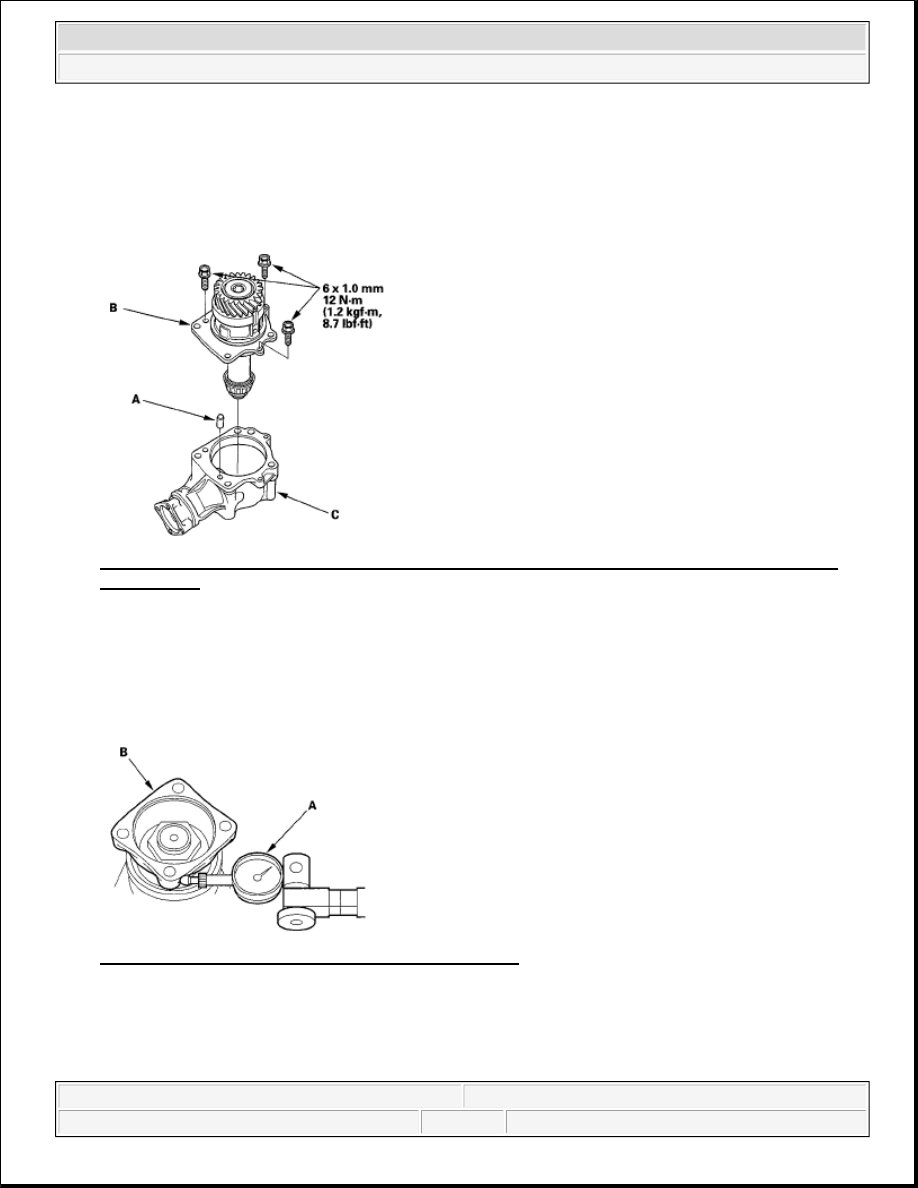
13. Install the dowel pin (A) and transfer holder assembly (B) in the transfer housing (C). 

Fig. 210: Identifying Dowel Pin, Transfer Holder Assembly And Transfer Housing With Torque 
Specification
 
Courtesy of AMERICAN HONDA MOTOR CO., INC. 

14. Rotate the companion flange several times to seat the tapered roller bearings.  

15. Set a dial indicator (A) on the companion flange (B), then measure the transfer gear backlash. 

Standard: 0.06-0.16 mm (0.002-0.006 in.)  

Fig. 211: Setting Dial Indicator On Companion Flange 
Courtesy of AMERICAN HONDA MOTOR CO., INC. 

16. Remove the transfer holder, and check the transfer drive gear tooth contact pattern. 

CORRECT TOOTH CONTACT PATTERN

NOTE:

Do not install the O-ring in this step.


2007 Honda Element EX 

2007-2008 TRANSMISSION Manual Transmission - Element


Fig. 212: Identifying Correct Tooth Contact Pattern 
Courtesy of AMERICAN HONDA MOTOR CO., INC. 

INCORRECT TOOTH CONTACT PATTERN  

Fig. 213: Identifying Incorrect Tooth Contact Pattern 
Courtesy of AMERICAN HONDA MOTOR CO., INC. 

17. If the transfer drive gear tooth contact is incorrect, adjust the transfer gear tooth contact with a 25 mm or 

35 mm thrust shim. If the gear tooth contact is correct, go to step 18. 

Toe Contact 

Use a thinner 35 mm thrust shim to move the transfer output shaft away from the transfer drive 
gear. Because this movement causes the transfer gear backlash to change, move the transfer drive 
gear toward the transfer output shaft to adjust the transfer gear backlash as follows:

NOTE:

Do not use more than one of each thrust shim to adjust the transfer drive 
gear tooth contact.


2007 Honda Element EX 

2007-2008 TRANSMISSION Manual Transmission - Element


Reduce the thickness of the 25 mm thrust shim.  

Increase the thickness of the 76 mm thrust shim by the amount you reduced the thickness of 
the 25 mm thrust shim.  

Heel Contact 

Use a thicker 35 mm thrust shim to move the transfer output shaft toward the transfer drive gear. 
Because this movement causes the transfer gear backlash to change, move the transfer drive gear 
away from the transfer output shaft to adjust the transfer gear backlash as follows: 

Increase the thickness of the 25 mm thrust shim.  

Reduce the thickness of the 76 mm thrust shim by the amount you increased the thickness of 
the 25 mm thrust shim.  

Flank Contact 

Use a thicker 25 mm thrust shim to move the transfer drive gear away from the transfer output 
shaft. Flank contact must be adjusted within the limits of the transfer gear backlash. If the backlash 
exceeds the limits, adjust as described under Heel Contact. 

Face Contact 

Use a thinner 25 mm thrust shim to move the transfer drive gear toward the transfer output shaft. 
Face contact must be adjusted within the limits of the transfer gear backlash. If the backlash 
exceeds the limits, adjust as described under Toe Contact. 

25 mm Thrust Shim  

THRUST SHIM THICKNESS CHART 

Shim No. Part Number

Thickness

1.70

29411-P1C-000 1.70 mm (0.067 in.)

1.73

29412-P1C-000 1.73 mm (0.068 in.)

1.76

29413-P1C-000 1.76 mm (0.069 in.)

1.79

29414-P1C-000 1.79 mm (0.070 in.)

1.82

29415-P1C-000 1.82 mm (0.072 in.)

1.85

29416-P1C-000 1.85 mm (0.073 in.)

1.88

29417-P1C-000 1.88 mm (0.074 in.)

1.91

29418-P1C-000 1.91 mm (0.075 in.)

1.94

29419-P1C-000 1.94 mm (0.076 in.)

1.97

29420-P1C-000 1.97 mm (0.078 in.)

2.00

29421-P1C-000 2.00 mm (0.079 in.)

2.03

29422-P1C-000 2.03 mm (0.080 in.)

2.06

29423-P1C-000 2.06 mm (0.081 in.)

2.09

29424-P1C-000 2.09 mm (0.082 in.)

2.12

29425-P1C-000 2.12 mm (0.083 in.)


2007 Honda Element EX 

2007-2008 TRANSMISSION Manual Transmission - Element


18. Measure the transfer gear backlash again.  

19. Remove the transfer holder assembly (A) from the transfer housing (B). 

Fig. 214: Identifying Transfer Holder Assembly And Transfer Housing 
Courtesy of AMERICAN HONDA MOTOR CO., INC. 

20. Securely clamp the transfer housing (A) in a bench vise (B) with wood blocks. 

Fig. 215: Identifying Transfer Housing And Bench Vise 
Courtesy of AMERICAN HONDA MOTOR CO., INC. 

21. Install the holder handle (C) and companion flange holder (D) on the companion flange, then loosen the 

transfer output shaft locknut.  

22. Remove the locknut (A), conical spring washer (B), and companion flange (C) from the transfer output 

2.15

29426-P1C-000 2.15 mm (0.085 in.)

2.18

29427-P1C-000 2.18 mm (0.086 in.)

2.21

29428-P1C-000 2.21 mm (0.087 in.)

2.24

29429-P1C-000 2.24 mm (0.088 in.)


2007 Honda Element EX 

2007-2008 TRANSMISSION Manual Transmission - Element


Content   ..  647  648  649  650   ..