Honda Element. Manual - part 611


  Index      Honda     Honda Element - service repair manual 2007-2008 year


Search            


Content   ..  609  610  611  612   ..


Honda Element. Manual - part 611


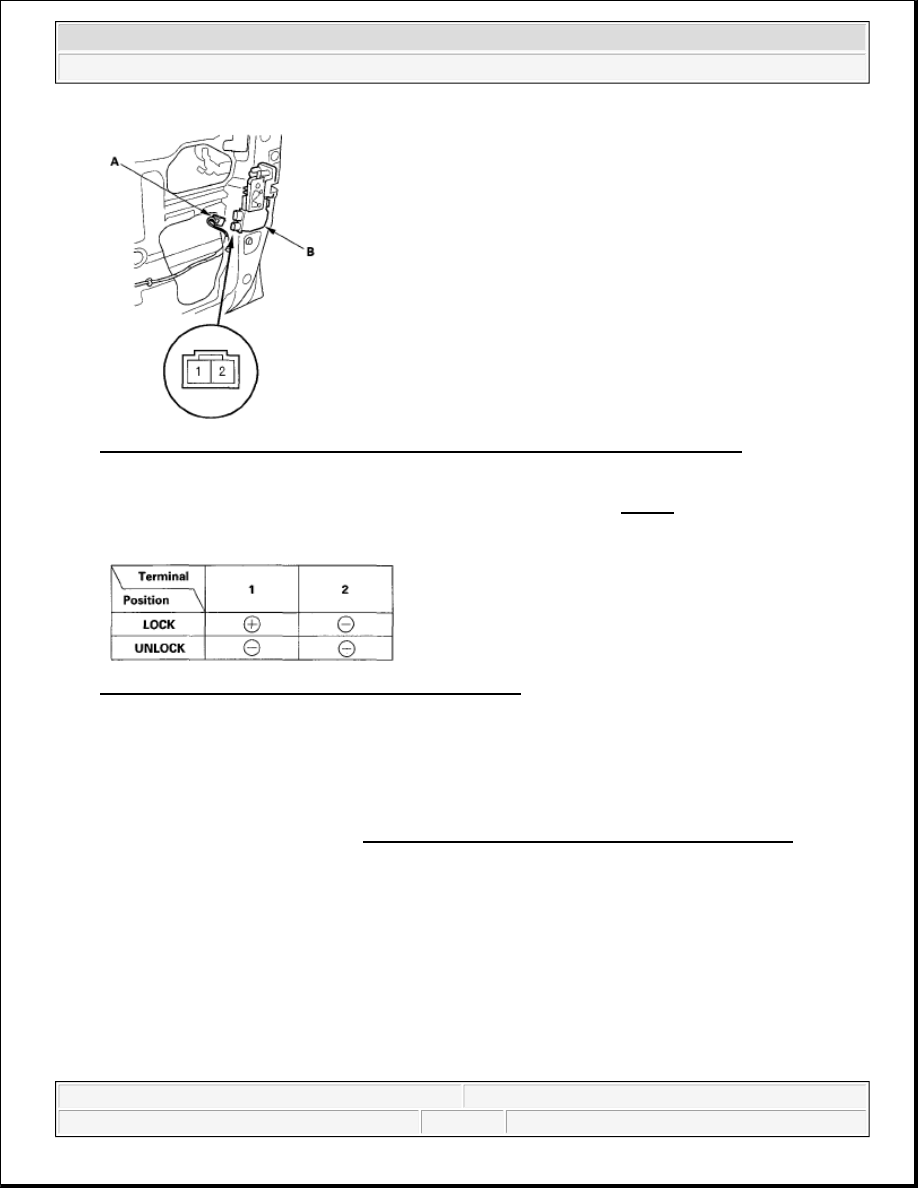
Fig. 9: Identifying Door Lock Actuator 2P Connector Terminals (Passenger's Door) 
Courtesy of AMERICAN HONDA MOTOR CO., INC. 

3. Check actuator operation by connecting power and ground according to Fig. 10. To prevent damage to 

the actuator, apply battery voltage only momentarily. 

Fig. 10: Battery Power And Ground Connection Chart 
Courtesy of AMERICAN HONDA MOTOR CO., INC. 

4. If the actuator does not work as specified, replace it.  

DOOR LOCK KNOB SWITCH TEST 

1. Remove the driver's door panel (see FRONT DOOR PANEL REMOVAL/INSTALLATION ).  

2. Disconnect the 3P connector (A) from the driver's door lock actuator (B). 


2007 Honda Element EX 

2007-08 ACCESSORIES AND EQUIPMENT Keyless/Power Door Lock System - Element


Fig. 11: Identifying Driver's Door Lock Actuator 3P Connector Terminals 
Courtesy of AMERICAN HONDA MOTOR CO., INC. 

3. Check for continuity between the terminals in each switch position according to Fig. 12

Fig. 12: Driver's Door Lock Actuator Terminals Continuity Chart 
Courtesy of AMERICAN HONDA MOTOR CO., INC. 

4. If the continuity is not as specified, replace the driver's door lock actuator.  

DOOR LOCK SWITCH TEST 

1. Remove the door panel (see FRONT DOOR PANEL REMOVAL/INSTALLATION ).  

2. Remove the two mounting screws and the door lock switch. 


2007 Honda Element EX 

2007-08 ACCESSORIES AND EQUIPMENT Keyless/Power Door Lock System - Element


Fig. 13: Identifying Door Lock Switch Mounting Screws And Door Lock Switch Terminals 
Courtesy of AMERICAN HONDA MOTOR CO., INC. 

3. Check for continuity between the No. 1 and No. 2 terminals: 

There should be continuity when the door lock switch is in the LOCKED position.  

There should be no continuity when the door lock switch is in the neutral or UNLOCKED position. 

4. Check for continuity between the No. 2 and No. 3 terminals: 

There should be continuity when the door lock switch is in the UNLOCKED position.  

There should be no continuity when the door lock switch is in the neutral or LOCKED position.  

5. If the continuity is not as specified, replace the door lock switch.  

REAR DOOR SWITCH TEST 

1. Remove the rear door panel (see REAR DOOR PANEL REMOVAL/INSTALLATION ).  

2. Disconnect the 2P connector (A) from the rear door upper and rear door lower switch. 


2007 Honda Element EX 

2007-08 ACCESSORIES AND EQUIPMENT Keyless/Power Door Lock System - Element


Fig. 14: Identifying Rear Door Switch 2P Connector Terminals 
Courtesy of AMERICAN HONDA MOTOR CO., INC. 

3. Check for continuity between the 2P connector terminals No. 1 and No. 2. 

There should be continuity with the rear door open.  

There should be no continuity with the rear door closed.  

4. If the continuity is not as specified, replace the faulty switch.  

HATCH LOCK ACTUATOR TEST 

1. Remove the hatch trim panel (see FRONT DOOR PANEL REMOVAL/INSTALLATION 9).  

2. Disconnect the 2P connector (A) from the actuator (B). 


2007 Honda Element EX 

2007-08 ACCESSORIES AND EQUIPMENT Keyless/Power Door Lock System - Element


Content   ..  609  610  611  612   ..