Honda Element. Manual - part 531


  Index      Honda     Honda Element - service repair manual 2007-2008 year


Search            


Content   ..  529  530  531  532   ..


Honda Element. Manual - part 531


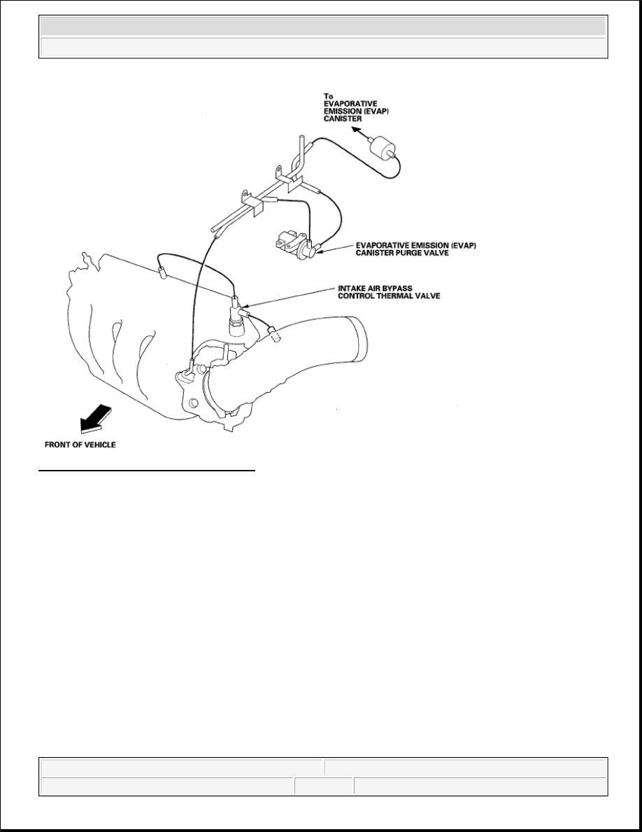
Fig. 18: Vacuum Hose Routing Diagram 
Courtesy of AMERICAN HONDA MOTOR CO., INC. 

VACUUM DISTRIBUTION 


2007 Honda Element EX 

2007-2008 ENGINE PERFORMANCE Fuel and Emissions Systems - Element


Fig. 19: Vacuum Distribution Diagram 
Courtesy of AMERICAN HONDA MOTOR CO., INC. 

ECM/PCM INPUTS AND OUTPUTS AT CONNECTOR A (31P) 


2007 Honda Element EX 

2007-2008 ENGINE PERFORMANCE Fuel and Emissions Systems - Element


Fig. 20: Identifying ECM/PCM Connector A (31P) 
Courtesy of AMERICAN HONDA MOTOR CO., INC. 

ECM/PCM CONNECTOR A REFERENCE 

NOTE:

Standard battery voltage is about 12 V.

Terminal 

number

Wire 
color

Terminal name

Description

Signal

1

WHT

KS (KNOCK SENSOR)

Detects knock sensor 
signal

With engine 
knocking: pulses

2

YEL/BLK IGP2 (POWER SOURCE)

Power source for 
ECM/PCM circuit

With ignition switch 
ON (II): battery 
voltage 
With ignition switch 
OFF: about 0 V

3

YEL/BLK IGP1 (POWER SOURCE)

Power source for 
ECM/PCM circuit

With ignition switch 
ON (II): battery 
voltage 
With ignition switch 
OFF: about 0 V

4

BLK

PG2 (POWER GROUND)

Ground circuit for 
ECM/PCM

Less than 1.0 V at all 
times

5

BLK

PG1 (POWER GROUND)

Ground circuit for 
ECM/PCM

Less than 1.0 V at all 
times

6

GRN

CMPB (CAMSHAFT 
POSITION SENSOR B)

Detects CMP sensor B 
signal

With engine running: 
pulses 
With ignition switch 
ON (II): about 5.0 V

7

YEL

CKP (CRANKSHAFT 
POSITION SENSOR)

Detects CKP sensor 
signal

With engine running: 
pulses 
With ignition switch 
ON (II): about 5.0 V

8

BRN/YEL LG2 (LOGIC GROUND)

Ground circuit for 
ECM/PCM

Less than 1.0 V at all 
times

9

BRN/YEL LG1 (LOGIC GROUND)

Ground circuit for 
ECM/PCM

Less than 1.0 V at all 
times


2007 Honda Element EX 

2007-2008 ENGINE PERFORMANCE Fuel and Emissions Systems - Element


Fig. 21: Identifying ECM/PCM Connector A (31P) 
Courtesy of AMERICAN HONDA MOTOR CO., INC. 

ECM/PCM CONNECTOR A REFERENCE 

10

BLK/WHT

AFSHTC (AIR FUEL RATIO 
(A/F) SENSOR HEATER 
CONTROL)

Drives A/F sensor 
heater

With ignition switch 
ON (II): battery 
voltage 
With fully warmed 
up engine running: 
about 0 V

13

BRN

IGPLS4 (No. 4 IGNITION COIL 
PULSE)

Drives No. 4 ignition 
coil

With ignition switch 
ON (II): about 0 V 
With engine running: 
pulses

14

WHT/BLU

IGPLS3 (No. 3 IGNITION COIL 
PULSE)

Drives No. 3 ignition 
coil

15

BLU/RED

IGPLS2 (No. 2 IGNITION COIL 
PULSE)

Drives No. 2 ignition 
coil

16

YEL/GRN

IGPLS1 (No. 1 IGNITION COIL 
PULSE)

Drives No. 1 ignition 
coil

18

BLU

NC (COUNTERSHAFT SPEED 
SENSOR)

Detects output shaft 
(countershaft) speed 
sensor signal

With ignition switch 
ON (II): about 0 V or 
about 5.0 V 
While driving: about 
2.5 V

19

BLU/WHT

CMPA (CAMSHAFT 
POSITION SENSOR A)

Detects CMP sensor A 
signal

With engine running: 
pulses 
With ignition switch 
ON (II): about 5.0 V

NOTE:

Standard battery voltage is about 12 V.

Terminal 

number

Wire color

Terminal name

Description

Signal

20

YEL/BLU VCC2 (SENSOR VOLTAGE)

Provides sensor 
voltage

With ignition switch ON 
(II): about 5.0 V 
With ignition switch OFF: 
about 0 V


2007 Honda Element EX 

2007-2008 ENGINE PERFORMANCE Fuel and Emissions Systems - Element


Content   ..  529  530  531  532   ..