Honda Element. Manual - part 251


  Index      Honda     Honda Element - service repair manual 2007-2008 year


Search            


Content   ..  249  250  251  252   ..


Honda Element. Manual - part 251


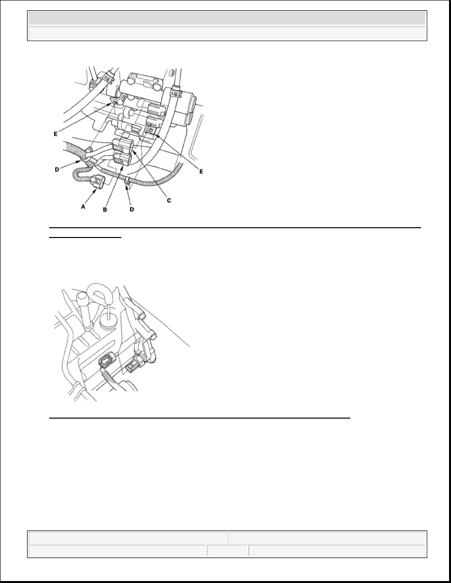
Fig. 270: Identifying Shift Solenoid Harness Connector And A/T Clutch Pressure Control Solenoid 
Valve B Connector
 
Courtesy of AMERICAN HONDA MOTOR CO., INC. 

35. Connect the 3rd clutch transmission fluid pressure switch connector. 

Fig. 271: Identifying 3rd Clutch Transmission Fluid Pressure Switch Connector 
Courtesy of AMERICAN HONDA MOTOR CO., INC. 

36. Connect the transmission range switch connector (A). 


2007 Honda Element EX 

2007-2008 TRANSMISSION Automatic Transmission - Element


Fig. 272: Identifying Transmission Range Switch Connector 
Courtesy of AMERICAN HONDA MOTOR CO., INC. 

37. Connect the input shaft (mainshaft) speed sensor connector (B) and output shaft (countershaft) speed 

sensor connector (C).  

38. Connect the A/T clutch pressure control solenoid valve A connector (A) and 2nd clutch transmission fluid 

pressure switch connector (B), and install the harness clamps (C) on the clamp brackets (D). 

Fig. 273: Identifying A/T Clutch Pressure Control Solenoid Valve A Connector And 2nd Clutch 
Transmission Fluid Pressure Switch Connector With Torque Specification
 
Courtesy of AMERICAN HONDA MOTOR CO., INC. 

39. Install the transmission ground terminal (E).  

40. Install the battery base, then install the harness clamp on the clamp bracket on the base.  

41. Refill the transmission with ATF (see step 5 ).  

42. Install the intake air duct and air cleaner assembly.  

43. Install the battery tray and battery, then secure the battery with its hold-down bracket.  

44. Clean the battery posts and cable terminals, then assemble them. 


2007 Honda Element EX 

2007-2008 TRANSMISSION Automatic Transmission - Element


45. Set the parking brake. Start the engine, and shift the transmission through all gears three times.  

46. Check the shift lever operation, A/T gear position indicator operation, and shift cable adjustment.  

47. Check and adjust the front wheel alignment (see WHEEL ALIGNMENT ).  

48. Install the splash shield.  

49. Start the engine in the P or N position, and warm it up to normal operating temperature (the radiator fan 

comes on).  

50. Turn off the engine, and check the ATF level (see ATF LEVEL CHECK ).  

51. Do the power window control unit reset procedure (see RESETTING THE POWER WINDOW 

CONTROL UNIT ).  

52. Do the road test (see ROAD TEST ).  

53. Loosen the bolts of the front mount, rear mount, and transmission mount after the road test.  

54. Tighten the transmission mount bolt to 54 N.m (5.5 kgf.m, 40 lbf.ft), tighten the rear mount bolt to 64 

N.m (6.5 kgf.m, 47 lbf.ft), and lastly tighten the front mount bolt to 64 N.m (6.5 kgf.m, 47 lbf.ft).  

55. Enter the anti-theft code for the audio system, then enter the audio presets, and set the clock.  

ATF COOLER CLEANING 

Special Tools Required  

ATF cooler cleaner GHTTTCF6H  

Magnetic nonbypass spin-on filter GTHGNBP2 (Available through the Honda Tool and Equipment 
Program 1-888-424-6857)  

Before installing an overhauled or remanufactured automatic transmission, you must thoroughly clean the ATF 
cooler to prevent system contamination. Failure to do so could cause a repeat automatic transmission failure. 

The cleaning procedure involves heated ATF-Z1 delivered under high pressure (100 psi). Check the security of 
all hoses and connections. Always wear safety glasses or a face shield, along with gloves and protective 
clothing. If you get ATF in your eyes or on your skin, rinse with water immediately. 

1. Check the fluid in the cooler cleaner tank. (The fluid level should be 4.5 inches from the top of the filler 

neck.) Adjust the level if needed; do not overfill. Use only Honda ATF-Z1; do not use any additives. 

WARNING:

Improper use of the ATF cooler cleaner can result in burns and other 
serious injuries.  

Always wear eye protection and protective clothing, and follow this 
procedure.  


2007 Honda Element EX 

2007-2008 TRANSMISSION Automatic Transmission - Element


Fig. 274: Checking Fluid In Cooler Cleaner Tank 
Courtesy of AMERICAN HONDA MOTOR CO., INC. 

2. Plug the cooler cleaner into a 110 V grounded electrical outlet. 

Fig. 275: Identifying Cooler Cleaner Into 110 V Grounded Electrical Outlet 
Courtesy of AMERICAN HONDA MOTOR CO., INC. 

3. Flip the HEAT toggle switch to ON; the green indicator above the toggle switch comes on. Wait 1 hour 

for the cooler cleaner to reach its operating temperature. (The cooler cleaner is ready to use when the 
temperature gauge reads 140 to 150°F.) 

4. Select the appropriate pair of fittings, and attach them to the radiator, to the hoses, or to the banjo bolts 

for flow through the ATF cooler cleaner. 

NOTE:

Make sure the outlet has no other appliances (light fixtures, drop lights, 
extension cords) plugged into it. Also, never plug the cooler cleaner into 
an extension cord or drop light; you would damage the unit.

NOTE:

If the red indicator above the HEAT toggle switch comes on, the fluid level 
in the tank is too low for the tank heater to work (see step 1 of this 
procedure).


2007 Honda Element EX 

2007-2008 TRANSMISSION Automatic Transmission - Element


Content   ..  249  250  251  252   ..