Honda Element. Manual - part 185


  Index      Honda     Honda Element - service repair manual 2007-2008 year


Search            


Content   ..  183  184  185  186   ..


Honda Element. Manual - part 185


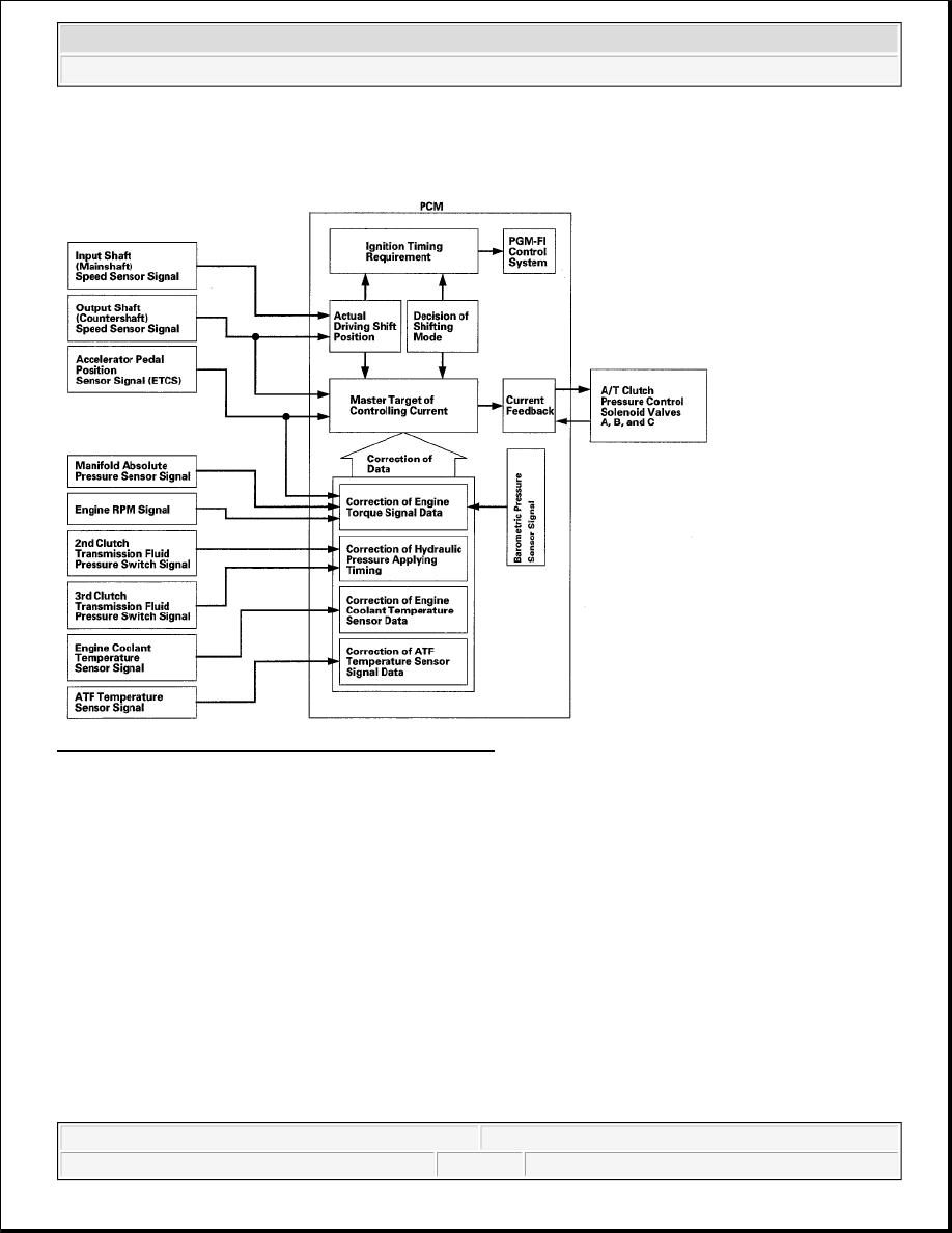
The PCM receives input signals from the various sensors and switches, processes data, and outputs a current to 
A/T clutch pressure control solenoid valves A, B, and C. 

Fig. 28: Clutch Pressure Control - Functional Diagram 
Courtesy of AMERICAN HONDA MOTOR CO., INC. 

Lock-up Control 

Shift solenoid valve E controls the hydraulic pressure to switch the lock-up shift valve and lock-up ON and 
OFF. The PCM actuates shift solenoid valve E and A/T clutch pressure control solenoid valve A to control the 
torque converter clutch lock-up. When shift solenoid valve E is turned ON, the lock-up condition starts. A/T 
clutch pressure control solenoid valve A regulates and apply the hydraulic pressure to the lock-up control valve 
to control the amount of the lock-up. The lock-up mechanism operates in 2nd, 3rd, 4th, and 5th gears in the D 
position, and 2nd and 3rd gears in the D position D3 driving mode.


2007 Honda Element EX 

2007-2008 TRANSMISSION Automatic Transmission - Element


Fig. 29: Lock-Up Control - Functional Diagram 
Courtesy of AMERICAN HONDA MOTOR CO., INC. 

PCM A/T Control System Electrical Connections 


2007 Honda Element EX 

2007-2008 TRANSMISSION Automatic Transmission - Element


Fig. 30: PCM A/T Control System - Circuit Diagram 
Courtesy of AMERICAN HONDA MOTOR CO., INC. 

PCM Connector Terminal Locations 


2007 Honda Element EX 

2007-2008 TRANSMISSION Automatic Transmission - Element


Fig. 31: Identifying PCM Connector Terminal 
Courtesy of AMERICAN HONDA MOTOR CO., INC. 

PCM CONNECTOR A (31P)  

PCM CONNECTOR TERMINAL REFERENCE 

Terminal number

Wire color

Terminal name

Description

Signal

A2

YEL/BLK

IGP2 (POWER 
SOURCE)

Power source for 
PCM circuit

With ignition 
switch ON (II): 
Battery voltage 
With ignition 
switch OFF: About 
0 V

A3

YEL/BLK

IGP1 (POWER 
SOURCE)

Power source for 
PCM circuit

With ignition 
switch ON (II): 
Battery voltage 
With ignition 
switch OFF: About 
0 V

A4

BLK

PG2 (POWER 
GROUND)

Ground circuit for 
PCM

Less than 1.0 V at 
all times

A5

BLK

PG1 (POWER 
GROUND)

Ground circuit for 
PCM

Less than 1.0 V at 
all times

A8

BRN/YEL

LG2 (LOGIC 
GROUND)

Ground circuit for 
PCM

Less than 1.0 V at 
all times

A9

BRN/YEL

LG1 (LOGIC 
GROUND)

Ground circuit for 
PCM

Less than 1.0 V at 
ail times

A18

BLU

NC (OUTPUT 
SHAFT 
(COUNTERSHAFT) 
SPEED SENSOR)

Detects output shaft 
(countershaft) speed 
sensor signal

With ignition 
switch ON (II): 
About 0 V or about 
5.0 V 
With vehicle 
moving: About 1.5-
3.5 V (pulses)

A20

YEL/BLU

VCC2 (SENSOR 
VOLTAGE)

Provides sensor 
reference voltage

With ignition 
switch ON (II): 


2007 Honda Element EX 

2007-2008 TRANSMISSION Automatic Transmission - Element


Content   ..  183  184  185  186   ..