Honda Element. Manual - part 183


  Index      Honda     Honda Element - service repair manual 2007-2008 year


Search            


Content   ..  181  182  183  184   ..


Honda Element. Manual - part 183


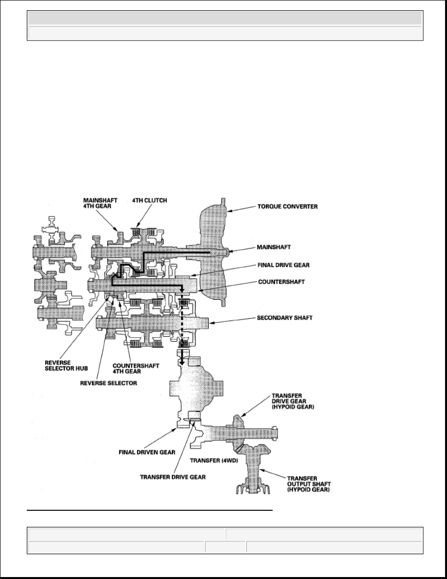
gear and reverse selector hub while the shift lever is in forward range (D, 2, and 1 positions). 

Hydraulic pressure is also applied to the 4th clutch, then the 4th clutch engages the mainshaft 4th gear 
with the mainshaft.  

The mainshaft 4th gear drives the countershaft 4th gear and the countershaft.  

Power is transmitted to the final drive gear, which in turn drives the final driven gear, and the transfer 
drive gear (4WD).  

4WD: The transfer drive gear drives the transfer drive gear (hypoid gear) and the transfer output shaft 
(hypoid gear).  

Fig. 21: Automatic Transmission Power Flow Diagram - 4th Gear 
Courtesy of AMERICAN HONDA MOTOR CO., INC.

NOTE:

The illustration shows the 4WD transmission; the 2WD transmission does not 
have the transfer mechanism.


2007 Honda Element EX 

2007-2008 TRANSMISSION Automatic Transmission - Element


5th Gear 

Hydraulic pressure is applied to the 5th clutch, then the 5th clutch engages the mainshaft 5th gear with the 
mainshaft.  

The mainshaft 5th gear drives the countershaft 5th gear and the countershaft.  

Power is transmitted to the final drive gear, which in turn drives the final driven gear, and the transfer 
drive gear (4WD).  

4WD: The transfer drive gear drives the transfer drive gear (hypoid gear) and the transfer output shaft 
(hypoid gear).  

Fig. 22: Automatic Transmission Power Flow Diagram - 5th Gear 
Courtesy of AMERICAN HONDA MOTOR CO., INC.

NOTE:

The illustration shows the 4WD transmission; the 2WD transmission does not 
have the transfer mechanism.


2007 Honda Element EX 

2007-2008 TRANSMISSION Automatic Transmission - Element


R Position 

Hydraulic pressure is applied to the servo valve to engage the reverse selector with the countershaft 
reverse gear and reverse selector hub while the shift lever is in the R position.  

Hydraulic pressure is also applied to the 4th clutch, then the 4th clutch engages the mainshaft reverse gear 
with the mainshaft.  

The mainshaft reverse gear drives the countershaft reverse gear via the reverse idler gear.  

The rotation direction of the countershaft reverse gear is changed by the reverse idler gear.  

The countershaft reverse gear drives the countershaft via the reverse selector, which drives the reverse 
selector hub.  

Power is transmitted to the final drive gear, which in turn drives the final driven gear, and the transfer 
drive gear (4WD).  

4WD: The transfer drive gear drives the transfer drive gear (hypoid gear) and the transfer output shaft 
(hypoid gear).  

NOTE:

The illustration shows the 4WD transmission; the 2WD transmission does not 
have the transfer mechanism.


2007 Honda Element EX 

2007-2008 TRANSMISSION Automatic Transmission - Element


Fig. 23: Automatic Transmission Power Flow Diagram - R Position 
Courtesy of AMERICAN HONDA MOTOR CO., INC. 

ELECTRONIC CONTROL SYSTEM 

Functional Diagram 

The electronic control system consists of the powertrain control module (PCM), sensors, and solenoid valves. 
Shifting and lock-up are electronically controlled for comfortable driving under all conditions. 

The PCM receives input signals from the sensors, switches, and other control units, processes data, and outputs 
signals for the engine control system and A/T control system. The A/T control system includes shift control, 
grade logic control, clutch pressure control, and lock-up control. 

The PCM switches the shift solenoid valves and the A/T clutch pressure control solenoid valves to control 
shifting transmission gears and lock-up torque converter clutch.


2007 Honda Element EX 

2007-2008 TRANSMISSION Automatic Transmission - Element


Content   ..  181  182  183  184   ..