Honda Element. Manual - part 152


  Index      Honda     Honda Element - service repair manual 2007-2008 year


Search            


Content   ..  150  151  152  153   ..


Honda Element. Manual - part 152


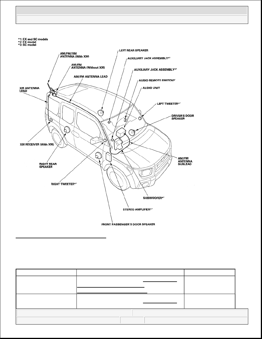
Fig. 2: Audio Component Location Index 
Courtesy of AMERICAN HONDA MOTOR CO., INC. 

SYMPTOM TROUBLESHOOTING INDEX 

SYMPTOM TROUBLESHOOTING INDEX 

Symptom

Diagnostic procedure

Also check for

Poor AM or FM radio 
reception or interference 
(with XM)

Symptom Troubleshooting (see POOR AM OR 
FM RADIO RECEPTION OR 
INTERFERENCE (WITH XM)
 )

Antenna lead short or 
open in the wire

Poor AM or FM radio 
reception or interference 

Symptom Troubleshooting (see POOR AM OR 
FM RADIO RECEPTION OR 

Antenna lead short or 
open in the wire


2007 Honda Element EX 

2007-2008 ACCESSORIES AND EQUIPMENT Audio - Element


(without XM)

INTERFERENCE (WITHOUT XM) )

Power switch will not turn 
ON (No information display 
and no sound)

Symptom Troubleshooting (see POWER 
SWITCH WILL NOT TURN ON (NO 
INFORMATION DISPLAY AND NO 
SOUND)
 )


Radio stays powered with 
the ignition switch OFF

Symptom Troubleshooting (see RADIO STAYS 
POWERED WITH THE IGNITION SWITCH 
OFF
 )


No sound is heard from 
speaker(s) (display is 
normal)

Symptom Troubleshooting (see NO SOUND IS 
HEARD FROM SPEAKER(S) (DISPLAY IS 
NORMAL)
 )


Poor or no sound with XM 
radio (Audio unit does 
display XM channels)

Symptom Troubleshooting (see POOR OR NO 
SOUND WITH XM RADIO (AUDIO UNIT 
DOES DISPLAY XM CHANNELS)
 )


XM radio display is blank 
and no station information is 
displayed

Symptom Troubleshooting (see XM RADIO 
DISPLAY IS BLANK AND NO STATION 
INFORMATION IS DISPLAYED
 )


Audio system sound is weak 
or distorted (display is 
normal)

Symptom Troubleshooting (see AUDIO SYSTEM 
SOUND IS WEAK OR DISTORTED 
(DISPLAY IS NORMAL)
 )


Audio unit button 
illumination does not work

Symptom Troubleshooting (see AUDIO UNIT 
BUTTON ILLUMINATION DOES NOT 
WORK
 )


Radio preset memory is lost

Symptom Troubleshooting (see RADIO PRESET 
MEMORY IS LOST
 )


XM radio preset memory is 
lost

Symptom Troubleshooting (see XM RADIO 
PRESET MEMORY IS LOST
 )


Error code: XM NO 
SIGNAL or XM 
ANTENNA is displayed

Symptom Troubleshooting (see ERROR CODE: 
XM NO SIGNAL OR XM ANTENNA IS 
DISPLAYED
 )


Audio disc does not eject

Symptom Troubleshooting (see AUDIO DISC 
DOES NOT EJECT
 )


Audio disc does not load

Symptom Troubleshooting (see AUDIO DISC 
DOES NOT LOAD
 )


Radio tuner does not change 
stations

Symptom Troubleshooting (see RADIO TUNER 
DOES NOT CHANGE STATIONS
 )


Volume does not change

Symptom Troubleshooting (see VOLUME DOES 
NOT CHANGE
 )


Display does not dim or 
brighten with dimmer

Symptom Troubleshooting (see DISPLAY DOES 
NOT DIM OR BRIGHTEN WITH DIMMER
 )


Audio disc does not play

Symptom Troubleshooting (see AUDIO DISC 
DOES NOT PLAY
 )


Audio disc skips

Symptom Troubleshooting (see AUDIO DISC 
SKIPS
 )

Tire pressure (over-
inflated), disc smudged, 
dirty, or scratched


2007 Honda Element EX 

2007-2008 ACCESSORIES AND EQUIPMENT Audio - Element


SYSTEM DESCRIPTION 

OVERVIEW 

The Audio Unit acts as the "processor" for all audio functions. Select audio functions from the front panel. The 
audio display provides the current audio status. (See the owner's manual for more details.) 

The audio unit has a built-in EEPROM (electrically erasable programmable read-only memory). This memory 
holds the audio presets (AM/FM radio frequency, sound settings, etc.) even when the battery is disconnected. 

The XM receiver passes its signal to the audio unit. In addition, it communicates with the audio unit via the GA-
Net bus. Any open connections in the GA-Net bus circuit will cause audio functions to appear inoperative. 

GA-NET BUS CONFIGURATION 

The GA-Net bus passes audio commands throughout the audio components. These commands include hard 
button signals, audio/XM selections, and XM station and music title names. Because the entire bus is "daisy 
chained" between components (see Fig. 3 ), any open or short in the GA-Net bus harness will cause any or all of 
these functions to become inoperative. The addition of any audio accessory must maintain the continuity of the 
GA-Net bus by installing the "Y" cable included with the accessory kit. 

Fig. 3: GA-Net Bus Diagram 
Courtesy of AMERICAN HONDA MOTOR CO., INC. 

AUDIO UNIT CONNECTOR INPUTS AND OUTPUTS (LX MODEL) 

Audio remote switch does 
not work properly

Symptom Troubleshooting (see AUDIO 
REMOTE SWITCH DOES NOT WORK 
PROPERLY
 )


2007 Honda Element EX 

2007-2008 ACCESSORIES AND EQUIPMENT Audio - Element


Fig. 4: Identifying Audio Unit Connector Inputs And Outputs (LX Model) 
Courtesy of AMERICAN HONDA MOTOR CO., INC. 

CONNECTOR REFERENCE 

AUDIO UNIT CONNECTOR INPUTS AND OUTPUTS (EX AND SC MODELS) 

Cavity

Wire

Connects to

1

YEL/GRN

AM/FM antenna amplifier power supply

2

YEL/RED

ACC (Main stereo power supply)

5

PNK

Right rear speaker (+)

6

BLU/WHT

Left rear speaker (+)

7

GRN/YEL

Front passenger's door speaker (+)

8

GRN/BLK

Driver's door speaker (+)

9

RED/BLK

Lights-on signal

10

WHT/RED

Constant power

15

BLU/YEL

Right rear speaker (-)

16

BLU/BLK

Left rear speaker (-)

17

BLU/YEL

Front passenger's door speaker (-)

18

GRN

Driver's door speaker (-)

19

RED

Dash lights brightness controller

20

BLK

Ground (G503)


2007 Honda Element EX 

2007-2008 ACCESSORIES AND EQUIPMENT Audio - Element


Content   ..  150  151  152  153   ..