Honda Element. Manual - part 94


  Index      Honda     Honda Element - service repair manual 2007-2008 year


Search            


Content   ..  92  93  94  95   ..


Honda Element. Manual - part 94


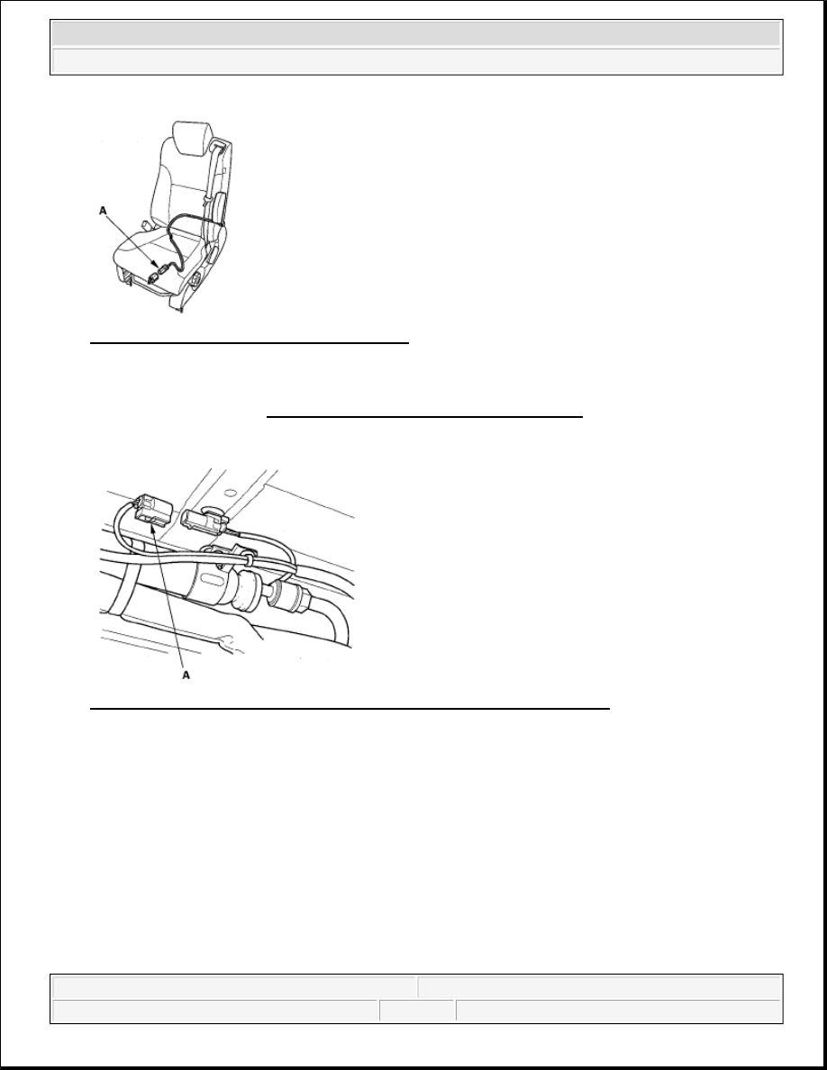
Fig. 27: Identifying Side Airbag 2P Connector 

Side Curtain Airbag  

5. Remove the headliner (see HEADLINER REMOVAL/INSTALLATION ).  

6. Disconnect both floor wire harness 2P connectors (A) from the side curtain airbags. 

Fig. 28: Identifying Side Curtain Airbag Floor Wire Harness 2P Connector 

Seat Belt Tensioner  

7. Disconnect both floor wire harness connectors (A) from the seat belt tensioners. 


2007 Honda Element EX 

2007-08 RESTRAINTS SRS (Supplemental Restraint System) - Element


Fig. 29: Identifying Seat Belt Tensioner Floor Wire Harness Connector 

Driver's seat shown; passenger's seat is similar. 

Seat Belt Buckle Tensioner  

8. Disconnect both floor wire harness connectors (A) from the seat belt buckle tensioner. 

Fig. 30: Identifying Seat Belt Buckle Tensioner Floor Wire Harness Connector 

Driver's seat shown; passenger's seat is similar. 

SRS Unit  

9. Remove the dashboard center lower cover (see CENTER LOWER COVER 

REMOVAL/INSTALLATION ). Disconnect SRS unit connector A (28P), SRS unit connector B (28P), 
and SRS unit connector C (28P) from the SRS unit. 


2007 Honda Element EX 

2007-08 RESTRAINTS SRS (Supplemental Restraint System) - Element


Fig. 31: Identifying SRS Unit Connectors 

GENERAL TROUBLESHOOTING INFORMATION 

DTC (DIAGNOSTIC TROUBLE CODES) 

The self-diagnostic function of the SRS system allows it to locate the causes of system problems and then store 
this information in memory. For easier troubleshooting, this data can be retrieved via a data link circuit. 

When you turn the ignition switch ON (II), the SRS indicator comes on. If it goes off after 6 seconds, the 
system is normal, and is not currently detecting any abnormality.  

If there is an abnormality, the system locates and defines the problem, stores this information in memory, 
and turns the SRS indicator on. The data will remain in the memory even when the ignition switch is 
turned off or if the battery is disconnected.  

The data is stored in memory as a diagnostic trouble code (DTC).  

The "x" at the end of each DTC denotes a numeric character (0 thru 9) or an alpha character (A thru F) 
that is displayed on the HDS.  

DTCs are either latching or resetting depending on the malfunction. With resetting DTCs, the SRS 
indicator will go off the next time the ignition switch is turned ON and the system is normal, but the DTC 
is still stored. With latching DTCs, the SRS indicator will not turn OFF until the malfunction is repaired 
and the DTC is cleared.  

When you connect the HDS to the 16P data link connector (DLC), you can retrieve a more detailed DTC 
in the Honda Systems "SRS" menu.  

After reading and recording the DTC, proceed with the troubleshooting procedure for that code.  

Precautions 

Use only a digital multimeter to check the system. If it's not a Honda multimeter, make sure its output is 
10 mA(0.01 A) or less when switched to the smallest value in the ohmmeter range. A tester with a higher 
output could damage the airbag circuit or cause accidental airbag deployment and possible injury.  

Whenever the ignition switch is ON (II), or has been turned OFF for less than 3 minutes, be careful not to 
bump the SRS unit; the airbags could accidentally deploy and cause damage or injuries.  

Make sure the battery is sufficiently charged. If the battery is dead or low, measuring values may not be 
correct.  

Do not touch a tester probe to the terminals in the SRS unit or harness connectors, and do not connect the 


2007 Honda Element EX 

2007-08 RESTRAINTS SRS (Supplemental Restraint System) - Element


SRS unit terminals or the sensor terminals with a jumper wire. Use only the backprobe set and the 
multimeter. Backprobe spring-loaded lock type connectors correctly.  

READING THE DTC 

1. Make sure the ignition switch is OFF.  

2. Connect the HDS to the data link connector (DLC) (A). 

Fig. 32: Identifying Data Link Connector 

3. Turn the ignition switch ON (II).  

4. Make sure the HDS communicates with the vehicle and the SRS unit. If it does not communicate, 

troubleshoot the DLC circuit (see DLC CIRCUIT TROUBLESHOOTING ).  

5. Use the HDS to check for SRS DTCs.  

6. Read and record the DTC.  

7. Turn the ignition switch OFF, and wait for 10 seconds.  

8. Disconnect the HDS from the DLC.  

9. Do the troubleshooting procedure for the DTC.  

CLEAR THE DTC MEMORY WITH THE HDS 

1. Make sure the ignition switch is OFF.  

2. Connect the HDS to the data link connector (DLC) (A). 


2007 Honda Element EX 

2007-08 RESTRAINTS SRS (Supplemental Restraint System) - Element


Content   ..  92  93  94  95   ..