Honda Element. Manual - part 92


  Index      Honda     Honda Element - service repair manual 2007-2008 year


Search            


Content   ..  90  91  92  93   ..


Honda Element. Manual - part 92


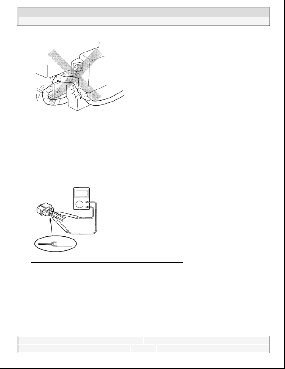
Fig. 13: Precaution For Installing Harness Wires 

Make sure all SRS ground locations are clean, and grounds are securely fastened for optimum metal-to-
metal contact. Poor grounds can cause intermittent problems that are difficult to diagnose.  

PRECAUTIONS FOR ELECTRICAL INSPECTIONS 

When using electrical test equipment, insert the probe of the tester into the wire side of the connector. Do 
not insert the probe of the tester into the terminal side of the connector, and do not tamper with the 
connector. 

Fig. 14: Inserting Probe Of Tester Into Wire Side Of Connector 

Use a U-shaped probe. Do not insert the probe forcibly. 


2007 Honda Element EX 

2007-08 RESTRAINTS SRS (Supplemental Restraint System) - Element


Fig. 15: Identifying U-Shaped Probe 

Use specified service connectors in troubleshooting. Using improper tools could cause an error in 
inspection due to poor metal-to-metal contact.  

SPRING-LOADED LOCK CONNECTOR 

Some SRS system connectors have a spring-loaded lock. 

Front Airbag Connectors 

Disconnecting 

To release the lock, pull the spring-loaded sleeve (A) toward the stop (B) while holding the opposite half of the 
connector. Then pull the connector halves apart. Be sure to pull on the sleeve and not on the connector. 

Fig. 16: Disconnecting Front Airbag Connectors 

Connecting 

To reconnect, hold the pawl-side connector, and press on the back of the sleeve-side connector in the direction 
shown. As the two connector halves are pressed together, the sleeve (A) is pushed back by the pawl (B). Do not 
touch the sleeve. 


2007 Honda Element EX 

2007-08 RESTRAINTS SRS (Supplemental Restraint System) - Element


Fig. 17: Connecting Front Airbag Connectors 

Side Airbag Connector 

Disconnecting 

To release the lock, pull the spring-loaded sleeve (A) toward the stop (B) while holding the opposite half of the 
connector. Then pull the connector halves apart. Be sure to pull on the sleeve and not on the connector half. 

Fig. 18: Disconnecting Side Airbag Connector 

Connecting 

Hold both connector halves, and press them firmly together until the projection (A) of the sleeve-side connector 
clicks. 


2007 Honda Element EX 

2007-08 RESTRAINTS SRS (Supplemental Restraint System) - Element


Fig. 19: Connecting Side Airbag Connector 

OPENING THE SRS UNIT SHORTING CONNECTORS FOR DIAGNOSIS 

Special Tools Required  

SRS short canceller 070AZ-SAA0100 

When SRS unit connectors A or C are disconnected, a short circuit is created in the connector by its own 
function to prevent an airbag deployment. The circuit may need to be open sometimes when diagnosis is 
performed on the system. Insert the short canceller (T/N 070AZ-SAA0100) in the specified cavities when it is 
necessary to keep the circuit open for diagnosis.

NOTE:

To prevent damaging the connector cavity, insert the short canceller 
straight into the cavity from the terminal side.  

Before installing the short canceller, wash it with electrical contact 
cleaner, then dry it with compressed air.  

Do not use the short canceller if it is damaged.  

Make sure to remove the short canceller before reconnection.  


2007 Honda Element EX 

2007-08 RESTRAINTS SRS (Supplemental Restraint System) - Element


Content   ..  90  91  92  93   ..