Honda Civic. Manual - part 1091


  Index      Honda     Honda Civic - service repair manual 2006-2009 year


Search            


Content   ..  1089  1090  1091  1092   ..


Honda Civic. Manual - part 1091


1. Turn the ignition switch ON (II).  
2. Clear the DTC with the HDS.  
3. Turn the ignition switch to LOCK (0), then turn it ON (II) again.  
4. Check for DTCs with the HDS. 

Is DTC 64-12 indicated?  

YES -Go to step 5. 

NO -Intermittent failure, the system is OK at this time. Check for loose 
terminals between the steering angle sensor 5P connector and the VSA 
modulator-control unit 37P connector. Refer to INTERMITTENT 
FAILURES TROUBLESHOOTING
 (see ). 

5. Turn the ignition switch to LOCK (0).  
6. Disconnect the steering angle sensor 5P connector.  
7. Disconnect the VSA modulator-control unit 37P connector.  
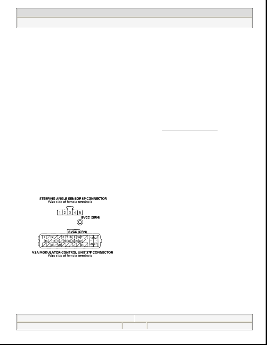
8. Check for continuity between VSA modulator-control unit 37P connector 

terminal No. 7 and steering angle sensor 5P connector terminal No. 5. 

Fig. 39: Checking Continuity Between VSA Modulator-Control Unit 7 
And Steering Angle Sensor 5P Connector Terminal No. 5
 

Is there continuity?  

YES -Go to step 9. 


2008 Honda Civic GX 

2006-08 BRAKES VSA System - Civic (All Except Hybrid)


NO -Repair open in the wire between the steering angle sensor and the VSA 
modulator-control unit. 

9. Turn the ignition switch ON (II).  

10. Measure voltage between steering angle sensor 5P connector terminal No. 5 

and body ground. 

Fig. 40: Measuring Voltage Between Steering Angle Sensor 5P Connector 
Terminal No. 5 And Body Ground
 

Is there 0.1 V or more?  

YES -Repair short to power in the wire between the steering angle sensor and 
the VSA modulator-control unit. 

NO -Check for loose terminals in the VSA modulator-control unit 37P 
connector. If necessary, substitute a known-good VSA modulator-control unit 
(see VSA MODULATOR-CONTROL UNIT REMOVAL AND 
INSTALLATION
 ), and retest. 

DTC 65-21: BRAKE FLUID LEVEL STUCK ON 

1. Turn the ignition switch ON (II).  
2. Clear the DTC with the HDS.  
3. Turn the ignition switch to LOCK (0), then turn it ON (II) again.  
4. Check for DTCs with the HDS. 

Is DTC 65-21 indicated?  


2008 Honda Civic GX 

2006-08 BRAKES VSA System - Civic (All Except Hybrid)


YES -Go to step 5. 

NO -Intermittent failure, the system is OK at this time. 

5. Release the parking brake.  
6. Turn the ignition switch to LOCK (0), then turn it ON (II) again.  
7. Check the brake system indicator in the gauge control module (tach). 

Does the indicator come on then go off?  

YES -Go to step 8. 

NO -Go to step 9. 

8. Check the FLUID LEVEL in the VSA DATA LIST with the HDS while 

moving the brake fluid reservoir tank float. 

Does it indicate ON when the float is lowered and OFF when the float is 
raised?
  

YES -Intermittent failure, the system is OK at this time. 

NO -Replace the VSA modulator-control unit (see VSA MODULATOR-
CONTROL UNIT REMOVAL AND INSTALLATION
 ). 

9. Check the brake fluid level in the master cylinder reservoir tank. 

Is the brake fluid level OK?  

YES -Go to step 10. 

NO -Do the brake pad inspection: Front (see INSPECTION - SI MODEL ), 
rear (see REAR BRAKE PAD INSPECTION AND REPLACEMENT ), 
check for brake fluid leaks or replace worn pads, then go to step 1 and recheck. 

10. Check the FLUID LEVEL in the VSA DATA LIST with the HDS while 

moving the brake fluid reservoir tank float. 


2008 Honda Civic GX 

2006-08 BRAKES VSA System - Civic (All Except Hybrid)


Does it indicate ON when the float is lowered and OFF when the float raised?  

YES -Go to step 11. 

NO -Replace the brake fluid reservoir tank (brake fluid level switch is 
included) (see MASTER CYLINDER INSPECTION ). 

11. Turn the ignition switch to LOCK (0).  
12. Disconnect the gauge control module (tach) 36P connector.  
13. Disconnect the brake fluid level switch 2P connector.  
14. Check for continuity between brake fluid level switch 2P connector terminal 

No. 2 and body ground. 

Fig. 41: Checking Continuity Between Brake Fluid Level Switch 2P 
Connector Terminal No. 2 And Body Ground
 

Is there continuity?  

YES -Repair short to body ground in the wire between the gauge control 
module (tach) and the brake fluid level switch. 

NO -Substitute a known-good gauge control module (tach), then go to step 1 
and recheck. If no DTCs are indicated, replace the original gauge control 
module (tach) (see REPLACEMENT ). 

DTC 66-11: PRESSURE SENSOR (INSIDE OF VSA MODULATOR-CONTROL UNIT) 
MALFUNCTION; DTC 66-12: PRESSURE SENSOR (INSIDE OF VSA MODULATOR-CONTROL 
UNIT) MALFUNCTION; DTC 66-13: PRESSURE SENSOR (INSIDE OF VSA MODULATOR-
CONTROL UNIT) MALFUNCTION; DTC 66-14: PRESSURE SENSOR (INSIDE OF VSA 
MODULATOR-CONTROL UNIT) MALFUNCTION; DTC 66-16: PRESSURE SENSOR (INSIDE OF 


2008 Honda Civic GX 

2006-08 BRAKES VSA System - Civic (All Except Hybrid)


Content   ..  1089  1090  1091  1092   ..