Honda Civic. Manual - part 70


  Index      Honda     Honda Civic - service repair manual 2006-2009 year


Search            


Content   ..  68  69  70  71   ..


Honda Civic. Manual - part 70


There should be an open circuit or at least 1 M ohms. 

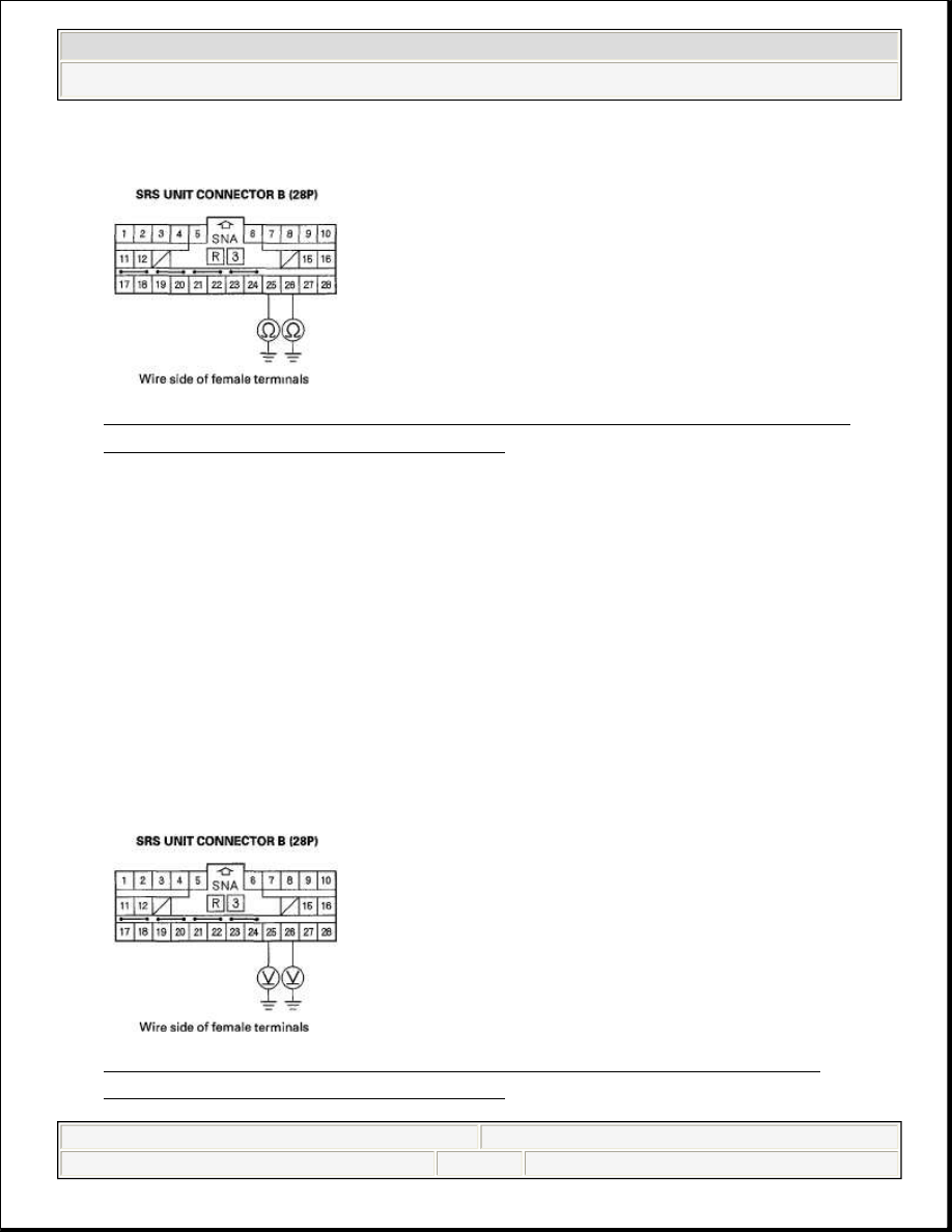
Fig. 168: Measuring Resistance Between No. 25 Terminal Of SRS Unit 
Connector B (28P) And Body Ground
 
Courtesy of AMERICAN HONDA MOTOR CO., INC. 

Is the resistance as specified?  

YES -Go to step 14. 

NO -Short to ground in the floor wire harness; replace the floor wire harness. 

14. Reconnect the negative cable to the battery.  
15. Turn the ignition switch ON (II).  
16. Measure the voltage between the No. 25 terminal of SRS unit connector B 

(28P) and body ground, and between the No. 26 terminal and body ground. 
There should be 1 V or less. 

Fig. 169: Measuring Voltage Between No. 25 Terminal Of SRS Unit 
Connector B (28P) And Body Ground


2008 Honda Civic EX 

2006-08 RESTRAINTS SRS (Supplemental Restraint System) - Civic (Except Hybrid)


Courtesy of AMERICAN HONDA MOTOR CO., INC. 

Is the voltage as specified?  

YES -Go to step 17. 

NO -Short to power in the floor wire harness; replace the floor wire harness. 

17. Turn the ignition switch OFF.  
18. Connect the SRS inflator simulator (jumper connector) and the black lead (A) 

of simulator lead L to the left side impact sensor 4P connector (B). 

Fig. 170: Identifying Left Side Impact Sensor 4P Connector 
Courtesy of AMERICAN HONDA MOTOR CO., INC. 

19. Measure the resistance between the No. 25 and No. 26 terminals of SRS unit 

connector B (28P). There should be 0-1.0 ohms. 

Fig. 171: Measuring Resistance Between No. 25 And No. 26 Terminals Of 


2008 Honda Civic EX 

2006-08 RESTRAINTS SRS (Supplemental Restraint System) - Civic (Except Hybrid)


SRS Unit Connector B (28P) 
Courtesy of AMERICAN HONDA MOTOR CO., INC. 

Is the resistance as specified?  

YES -Faulty left side impact sensor (first) or SRS unit; replace the left side 
impact sensor (first) (see SIDE IMPACT SENSOR (FIRST) 
REPLACEMENT
). If the problem is still present, replace the SRS unit (see 
SRS UNIT REPLACEMENT). 

NO -Open in the floor wire harness; replace the floor wire harness. 

DTC 44-1X ("X" CAN BE 0 THRU 9 OR A THRU F): NO SIGNAL FROM THE RIGHT SIDE 
IMPACT SENSOR (FIRST) 

Special Tools Required  


SRS inflator simulator 07SAZ-TB4011A  


SRS simulator lead L 070AZ-SNAA300  

1. Clear the DTC memory (see CLEAR THE DTC MEMORY WITH THE 

HDS).  

2. Turn the ignition switch ON (II), then wait for 10 seconds.  
3. Read the DTC (see CLEAR THE DTC MEMORY WITH THE HDS). 

Is DTC 44-11 indicated?  

YES -Go to step 5. 

NO -Go to step 4. 

4. Read the DTC. 

NOTE:

Before doing this troubleshooting procedure, review SRS 
Precautions and Procedures (see PRECAUTIONS AND 
PROCEDURES) and General Troubleshooting Information 
(see GENERAL TROUBLESHOOTING INFORMATION).


2008 Honda Civic EX 

2006-08 RESTRAINTS SRS (Supplemental Restraint System) - Civic (Except Hybrid)


Is DTC 44-12 indicated?  

YES -Faulty right side impact sensor (first); replace the right side impact 
sensor (first) (see SIDE IMPACT SENSOR (FIRST) REPLACEMENT). 

NO -Intermittent failure, system is OK at this time. Go to 
TROUBLESHOOTING INTERMITTENT FAILURES. If DTC 44-1x 
except DTC 44-11 and 44-12 is indicated, faulty right side impact sensor 
(first). Replace the right side impact sensor (first) (see SIDE IMPACT 
SENSOR (FIRST) REPLACEMENT
). 

5. Turn the ignition switch OFF.  
6. Disconnect the negative cable from the battery, then wait for 3 minutes.  
7. Disconnect both seat belt tensioner connectors (see step 7 DISCONNECTING 

SYSTEM CONNECTORS) and both seat belt buckle tensioner connectors 
(see step 8 DISCONNECTING SYSTEM CONNECTORS ).  

8. Disconnect the floor wire harness 4P connector (A) from the right side impact 

sensor (first). 

Fig. 172: Identifying Floor Wire Harness 4P Connector 
Courtesy of AMERICAN HONDA MOTOR CO., INC. 

9. Disconnect SRS unit connector B (28P) from the SRS unit (see step 9 

DISCONNECTING SYSTEM CONNECTORS).  

10. Measure the resistance between the No. 27 and No. 28 terminals of SRS unit 

connector B (28P). There should be an open circuit or at least 1 M ohms. 


2008 Honda Civic EX 

2006-08 RESTRAINTS SRS (Supplemental Restraint System) - Civic (Except Hybrid)


Content   ..  68  69  70  71   ..