Dongfeng DFA1063DJ10 (14)-301/303. Manual - part 8
Transmission
MT-7
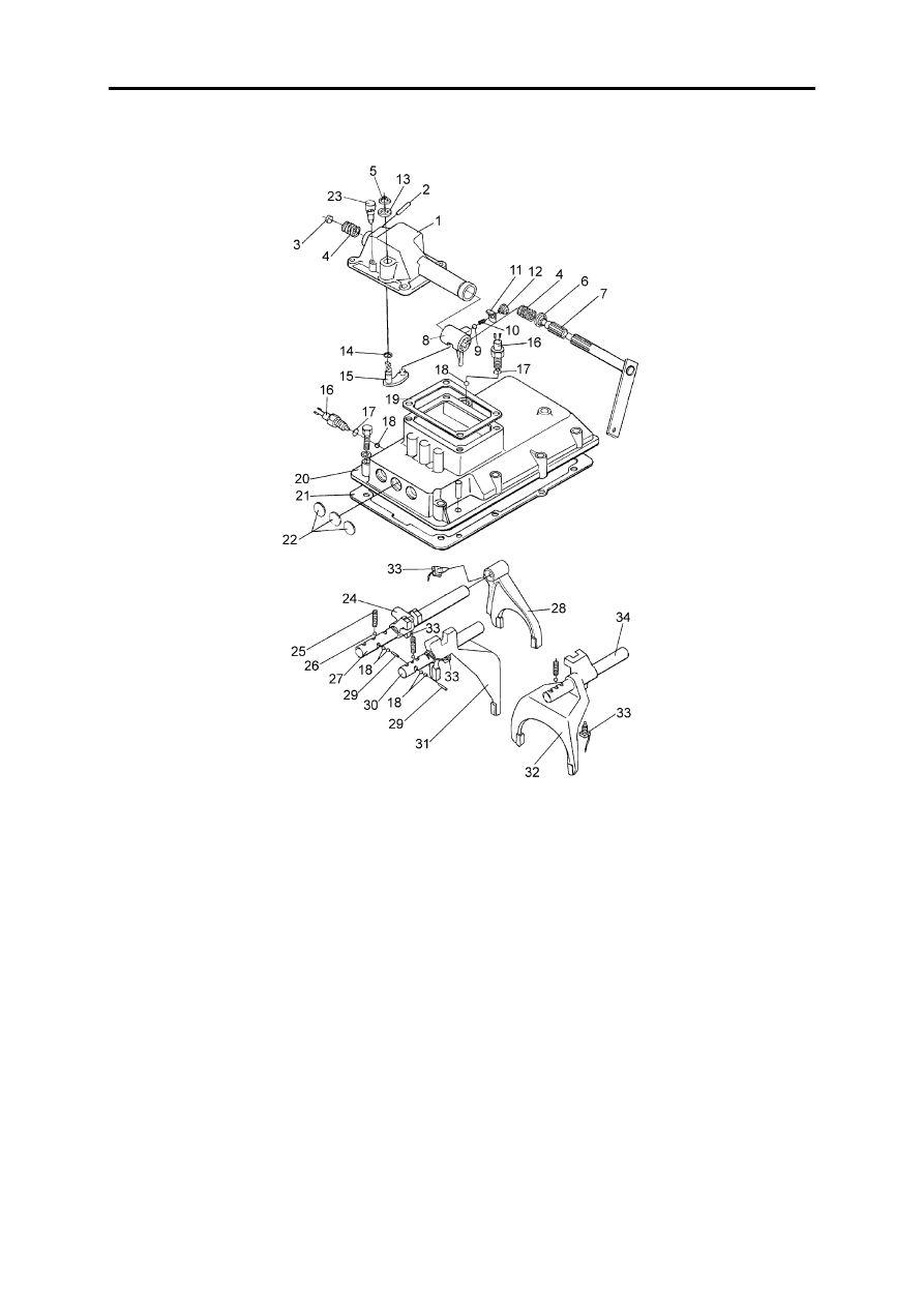
Transmission cover
1.Cover
2.Straight pin
3.Bell cap
4.Balancing spring--selecting shaft
5.Circlip for shaft
6.Oil seal--transmission cover
7.Control shaft and gear shift arm assy
8.Transmission shift lever
9.Steel ball
10.Damping spring--reverse gear
11.Lock shim--spring seat
12.Damping spring seat--reverse gear
13.Washer
14.O-ring
15.Gear selecting rotating arm assy
16.Switch assy
17.Sealing ring
18.Steel ball
19.Gasket spacer--cover
20.Transmission upper cover
21.Gasket spacer--upper cover
22.Spacer
23.Vent plug assy
24.Guide block--1st, reverse gear
25.Locking gear shift fork shaft spring
26.Steel ball
27.Gear shift fork shaft --1st, reverse gear
28.Gear shift fork --1st, reverse gear
29.Straight pin--interlock
30.Gear shift fork shaft--2nd, 3rd gear
31.Gear shift fork--2nd, 3rd gear
32.Gear shift fork--4th, 5th gear
33.Locking bolt--gear shift fork
34.Gear shift fork shaft--4th, 5th gear