Dongfeng EQ1030T47D-820. Manual - part 16


  Index      Dongfeng     Dongfeng EQ1030T47D-820 Light Commercial Truck - service repair manual 2006 year


Search            


Content   ..  14  15  16  17   ..


Dongfeng EQ1030T47D-820. Manual - part 16


Front suspension

FA-16

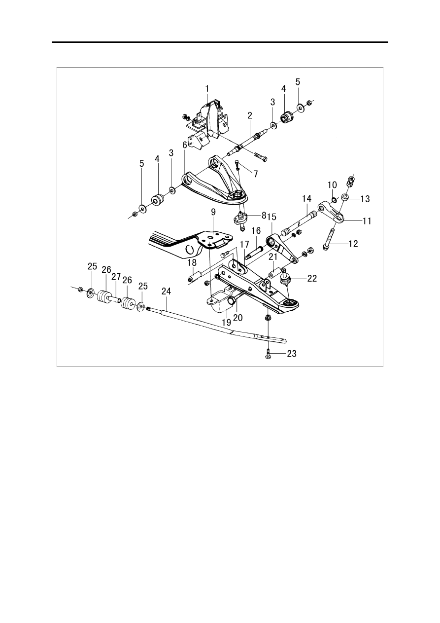
Front Independent Suspension

When assembling the rubber part, the final tightening has to be under such condition: wheel on the ground,

no load. 

Condition of no load: with full fuel, coolant, engine lubricant, and the spare tyre, jack, driver tool on the

vehicle, and the vehicle park on the level position.

1.

Shock absorber assy

2.

Upper arm shaft

3.

Inner side washer

4.

Rubber bush assy

5.

Big washer

6.

Upper transverse arm

7.

Bolt

8.

Round head pin assy

9.

Front suspension cross member assy

10.

Circlip for holes

11.

Torsion bar adjusting arm

12.

Adjust bolt

13.

Round head

14.

Front torsion bar spring

15.

Torsion bar fixing bar

16.

Lower arm shaft

17.

Lower transverse arm assy

18.

Rubber bush assy

19.

Limit block assy

20.

Bolt

21.

Rubber bush assy

22.

Round head pin assy

23.

Bolt

24.

Propelling rod

25.

Big washer

26.

Rubber bush

27.

Spacer sleeve

Front suspension

FA-17

Shock absorber

Disassembly and assembly

When disassembling and assembling the shock

absorber, never let the oil or grease touch the rubber parts.

Check

Use the proper cleanser to wash all the parts except the non-metal parts, and then dry them with compressed

air.

Make use of the compressed air to clean the non-metal parts.

Check the shock absorber for loose or crack ad oil leakage, replace if necessary.

Check the piston lever for crack, deform, or other damages, replace if necessary.

Check the rubber parts for wear, crack, damage or deform, replace if necessary.

Torsion bar spring
Disassembly

Make a location mark between the torsion bar and its

adjusting arm and the fixed arm.

Measure the length of the extruding part of the

adjusting bolt.

Front suspension

FA-18

Disassemble the torsion bar adjusting arm from

behind and draw out the torsion bar.

Disassemble the torsion bar fixed arm.

Check

Check the torsion bar for any wear, deform, bend or any other damages.

Check the parts serrating spline for crack, wear, distort or other danages.

Assembly and adjustment

Along the tightening direction to adjust the adjusting nut of the adjusting arm. Never adjust the nut along the

nut loose direction. 

1.Install the torsion bar fixed arm to the lower trans-

verse arm.

2.Wipe a layer of grease on the spline tooth of the tor-

sion bar.

3.Adjust the lower transverse arm position to assure

the alignment of both the torsion bar mark and its adjusting
arm mark.

Front suspension

FA-19

4.Install the torsion bar spring

When install the torsion bar spring, please pay atten-

tion to the mark on the end of the spring. Don't install in
wrong direction.

5.Install the adjusting arm

Make sure the vehicle is in no load.

Make the same extending length of the fixed bolt and

the extending length before disassembling, and then
screw down.

Tighten or loose the adjusting nut to adjust the

vehicle gesture, and before tightening, there should be
loose first and then tighten up as required.

After adjusting the vehicle body gesture, tighten the

locking nut to the required torque.

Tightening torque: 108~127N.m

6. With the wheel on ground (vehicle no load), shock

the vehicle to eliminate the friction force of the suspension
parts.

7.Measure the vehicle gesture  H

H=A-B mm (no load)

See "Maintenance data & explanation" for reference.


Content   ..  14  15  16  17   ..