Chrysler Le Baron, Dodge Dynasty, Plymouth Acclaim. Manual - part 289


  Index      Dodge     Chrysler Le Baron, Dodge Dynasty, Plymouth Acclaim - service repair manual 1993 year


Search            


Content   ..  287  288  289  290   ..


Chrysler Le Baron, Dodge Dynasty, Plymouth Acclaim. Manual - part 289


INSTALLATION

(1) Position distributor in engine. Make certain that

the O-ring is properly seated on distributor. If O-ring is
cracked or nicked, replace it with new one.

(2) Carefully engage distributor drive with auxiliary

shaft drive. When distributor is installed properly,
rotor will be pointing toward cylinder block. If engine
has been cranked while distributor is removed,
establish proper relationship between the dis-
tributor shaft and Number 1 piston position as
follows:

(a) Rotate the crankshaft until number one piston

is at top of compression stroke. Pointer on clutch
housing should be in line with the O(TDC) mark on
flywheel.

(b) Rotate rotor to a position just ahead of the

number one distributor cap terminal.

(c) Lower the distributor into the opening, engag-

ing distributor drive with drive on auxiliary shaft.

With distributor fully seated on engine, rotor should
be under the cap number 1 tower.
(3) Install the distributor cap. Ensure all high ten-

sion wires snap firmly in the cap towers.

(4) Install hold-down arm screw and finger tighten.
(5) Install splash shield.
(6) Connect distributor pick-up connector lead wire

at wiring harness connector.

(7) Set ignition timing to specification. Refer to Ig-

nition Timing.

DISTRIBUTOR PICK-UP—2.2L TBI, 2.5L TBI AND
2.5L MPI ENGINES

REMOVAL

(1) Remove splash shield and cap. Refer to Distribu-

tor Removal.

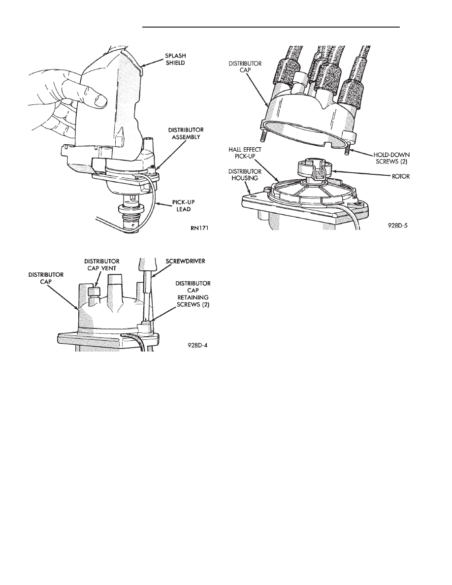
(2) Remove rotor from shaft (Fig. 15).
(3) Remove Hall effect pick-up assembly (Fig.

16).

INSTALLATION

(1) Place pick-up assembly into distributor housing

(Fig. 16).

The distributor pick-up wires may be damaged

if not properly reinstalled.

(2) Install rotor (Fig. 15).
(3) Install cap and splash shield. Refer to Distribu-

tor Installation.

DISTRIBUTOR SERVICE—3.0L ENGINE

REMOVAL

(1) Disconnect distributor connector from wiring

harness connector (Fig. 17).

Fig. 12 Splash Shield—2.5L Engine

Fig. 13 Distributor Cap Retaining Screws—2.5L En-

gine

Fig. 14 Distributor Cap—2.5L Engine

8D - 18

IGNITION SYSTEMS

Ä

(2) Loosen distributor cap retaining screws.
(3) Lift cap of off distributor (Fig. 18).
(4) Rotate engine crankshaft until the distributor

rotor points the intake manifold plenum. Scribe a
mark on the plenum in line with the rotor. The
scribe line indicates where to position the rotor when
reinstalling the distributor.

(5) Remove distributor hold down nut (Fig. 19).
(6) Carefully lift the distributor from the engine.

INSTALLATION

(1) Position distributor in engine. Make certain

that the O-ring is properly seated on distributor. If
O-ring is cracked or nicked replace with new one.

Fig. 15 Ignition Rotor—2.2L TBI, 2.5L TBI and 2.5L

MPI Engines

Fig. 16 Hall Effect Pickup Assembly—2.2L TBI, 2.5L

TBI and 2.5l MPI Engines

Fig. 17 Distributor Electrical Connector—3.0L

Engine

Fig. 18 Distributor Cap—3.0L Engine

Fig. 19 Distributor Hold-Down—3.0L Engine

Ä

IGNITION SYSTEMS

8D - 19

(2) Carefully engage distributor drive with gear on

camshaft. When the distributor is installed properly,
the rotor will be in line with previously scribe line on
air intake plenum. If engine was cranked while
distributor was removed, establish proper rela-
tionship between the distributor shaft and Num-
ber 1 piston position as follows:

(a) Rotate the crankshaft until number one piston

is at top of compression stroke.

(b) Rotate rotor to number one rotor terminal (Fig.

20).

(c) Lower the distributor into the opening, engag-

ing distributor drive with drive on camshaft. With
distributor fully seated on engine, rotor should be
under the number 1 terminal (Fig. 20).

(3) Install distributor cap. Ensure sure all high

tension wires are firmly in the cap towers.

(4) Install hold-down nut and finger tighten.
(5) Connect distributor electrical connector to wiring

harness connector (Fig. 17).

(6) Set ignition timing to specification. Refer to Ig-

nition Timing in this section.

DISASSEMBLY

(1) Remove distributor cap mounting screws (Fig.

18).

(2) Remove distributor cap and inspect for flashover,

cracked carbon button, cracked cap, or burned termi-
nals. If any of these conditions exist, replace cap.

(3) Remove rotor screw (Fig. 21). Inspect rotor for

cracks or burned electrode. If any of these conditions
exist, replace rotor.

(4) Remove protective cover from distributor hous-

ing (Fig. 22).

(5) Remove lead wire clamp screw and remove lead

wire (Fig. 23).

(6) Remove disk assembly screw (Fig. 24).
(7) Remove disk spacers and disk (Fig. 25). Disk

and spacers are keyed. Check disk for warpage,
cracks or damaged slots (Fig. 26).

(8) Remove bushing and photo optic sensing unit

fasteners. Remove unit from distributor housing (Fig.
27).

(9) Remove bearing retainer screws (Fig. 28).

Fig. 21 Rotor Screw

Fig. 22 Protective Cover

Fig. 23 Lead Wire Clamp

Fig. 20 Distributor Cap Terminal Routing, View from

Top of Cap—3.0L Engine

8D - 20

IGNITION SYSTEMS

Ä

(10) Make reassembly alignment marks on gear

and shaft (Figs. 29 and 30).

(11) With a pin punch drive out distributor drive

gear roll pin (Fig. 31).

(12) Remove distributor drive gear (Fig. 32).

(13) Remove distributor shaft and bearing assem-

bly (Fig. 33).

(14) To reassemble, reverse preceding procedure.

Refer to Fig. 34.

Fig. 24 Disk Assembly Screw

Fig. 25 Disk and Spacers Installed

Fig. 26 Disk and Spacers

Fig. 27 Photo Optic Sensing Unit Assembly and

Bushing

Fig. 28 Bearing Retainer Screws

Fig. 29 Marking Drive Gear and Shaft

Ä

IGNITION SYSTEMS

8D - 21


Content   ..  287  288  289  290   ..