Saturn Transmission. Manual - part 17
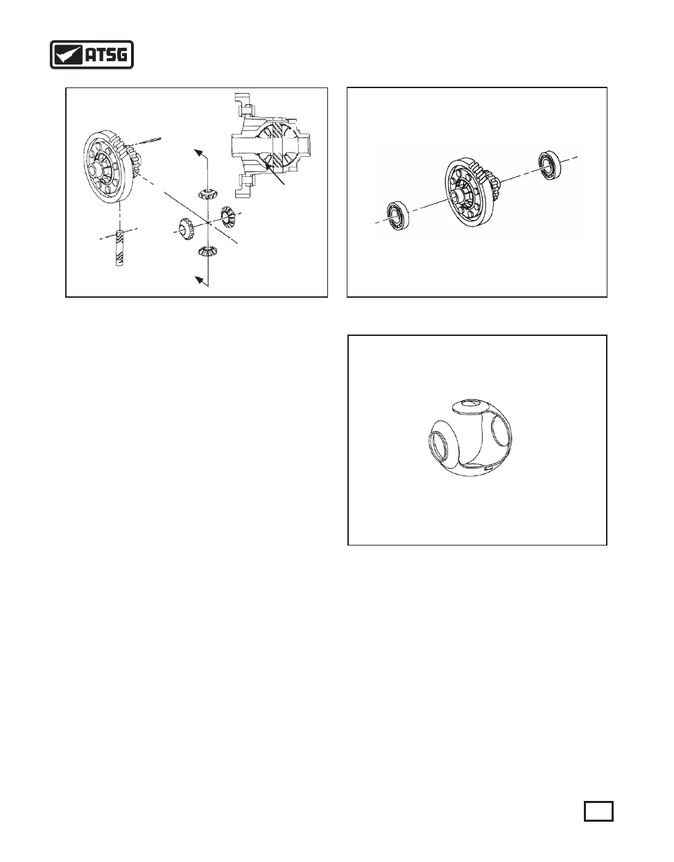
Figure 157
DIFFERENTIAL DISASSEMBLY
1. Using a suitable drift pin, drive the roll pin from
the differential housing and remove the pinion
shaft and side gears (See Figure 157).
2. Rotate the pinion gears and remove them from the
housing (See Figure 157).
3. Remove the plastic side gear liner from the
housing (See Figure 159).
4. Inspect the pinion shaft for wear, the side gears for
wear and the side gear liner for wear. Replace
if necessary.
5. Inspect the differential side bearings for wear and
pit marks and replace if necessary. To remove the
bearings, use a suitable puller (See Figure 158).
A) To remove the speed sensor side bearing, a
typical puller can be used.
B) To remove the differential gear side bearing,
use a two jaw puller. Place a shield over the
bearing to provide protection if the bearing
should break.
DIFFERENTIAL ASSEMBLY
1. NOTICE: The bearing on the right side (The
vehicle speed sensor side) of the differential has
a black colored cage. (Service bearings
however, will all have a black cage and are
interchangeable).
2. Press the new differential bearings onto the
differential housing using Saturn's tool SA9120T
or equivalent. Check to be sure that the bearings
are fully seated.
3. Install the side gear liner into the housing. Position
the liner inside the housing so that the side gear
section with the alignment tabs set into the pocket
on the ring gear side of the case.
Figure 158
SIDE GEAR
LINER
4. Place the side gears into position in the housing
and hold in position.
5. Install one of the pinion gears on the tabbed side
of the thrust liner and then pull the thrust liner
partially over the pinion gear to hold it into place.
6. Place the second pinion gear into position, directly
opposite from the first pinion gear. Rotate the
thrust liner until the pinion gear holes line up with
the shaft holes in the housing.
7. Install the side gears into the housing.
8. Install the pinion shaft and a new roll pin. Be sure
to drive the roll pin flush to the housing
preventing any interference with the speed sensor
signal.
9. Install the differential assembly into the converter
housing case half.
Figure 159
71
AUTOMATIC TRANSMISSION SERVICE GROUP
Technical Service Information