Saturn Transmission. Manual - part 15


  Index      Saturn     Saturn Transmission - service manual


Search            


Content   ..  13  14  15  16   ..


Saturn Transmission. Manual - part 15


         installer kit number is SA9143T. It consists of:
         SA9144T-1 - The re-sizer
         SA9144T-2 - Long expander
         SA9144T-3 - Medium expander
         SA9144T-4 - Short expander
   20. After the rings are installed, use the seal sizer by
         rotating the tool and pushing lightly onto one seal
         at a time until all three rings have been re-sized 
         (See Figure 129).
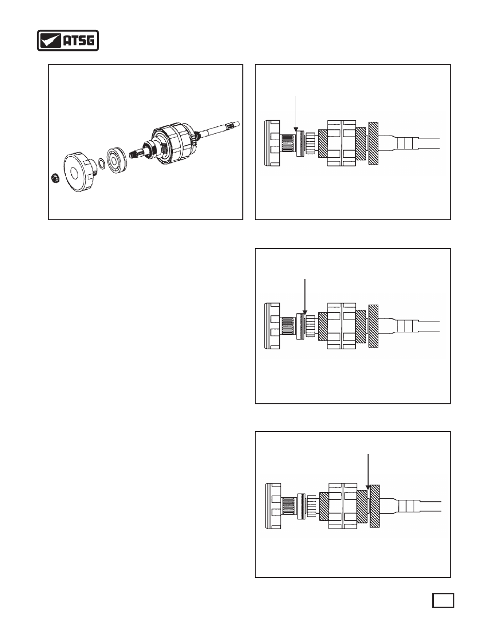
   21. Install the input shaft bearing, 1st drive gear to 
         case thrust washer and 1st clutch housing assembly
         onto the input shaft (See Figure 130).
   22. Torque the end nut to 150 N m (111 ft lbs).
   23. Using a feeler gauge, check the clearance between
         the 1st drive gear and case bearing (See Figure
         131). The clearance should be:
         0.075 mm - 0.425 mm  or
         0.003 in.   - 0.017 in.
   24. Using a feeler gauge, check the clearance between
          the 2nd/Rev drive gear and the 2nd/Rev thrust
          bearing (See Figure 132). The clearance should
          be:
          0.032 mm - 0.144 mm  or
          0.001 in.   - 0.006 in.
   25. Using a feeler gauge, check the clearance between
         the 4th drive gear and the 3/4 drive gear thrust
         bearing (See Figure 133). The clearance should be:
         0.057 mm - 0.219 mm  or
         0.002 in.   - 0.009 in.
         IMPORTANT: There are no selective washers to
         adjust end play. If clearance is not within
         specifications, there is either a misassembly 
         problem or worn parts.   
  

 26. Remove the first clutch drum assembly and case 

         bearing and set aside for later transaxle
         reassembly.

Figure 130

Figure 131

Figure 132

Figure 133

63

AUTOMATIC TRANSMISSION SERVICE GROUP

Technical Service Information

OUTPUT SHAFT ASSEMBLY AND THRUST WASHER OVERVIEW

Figure 134

1st Driven Gear

Thrust Washer

Reverse Driven Gear

Thrust Washer

Groove Towards 

Reverse Driven Gear

Reverse

Driven

Gear

Wide End of Slots

Towards 2nd Driven Gear

2nd Driven

Gear

Bearing Eliminated During

1992 Model Year Production

2nd Driven Gear

Thrust Washer

4th Driven Gear

Thrust Washer

3rd Driven Gear

Split Washer

Third Driven

Gear

4th Driven

Gear

1st Driven

 Gear

64

AUTOMATIC TRANSMISSION SERVICE GROUP

Technical Service Information

Figure 137

Figure 136

Figure 135

OUTPUT SHAFT ASSEMBLY
     1. Install two output shaft to 4th clutch housing O
         ring seals on the output shaft and lubricate with
         petroleum jelly generously (See Figure 135).
     2. Carefully slide the 4th clutch housing assembly
         over the O rings and hand press the drum down 
         until it is up against the pinion gear (See Figure
         135).
     3. Install 4th driven gear thrust washer. The washer
         has internal splines which key to the splines on
         the shaft just above the 4th clutch housing. If the
         housing is not down all the way, the washer will 
         not have splines to key onto (See Figure 136).
     4. Install caged needle bearing (See Figure 136).
     5. Install the double sided needle bearing thrust
         washer with the open face towards the 4th driven
         gear (See Figure 136).
     6. Install 4th drive gear by rotating the gear back 
         and forth until all the fiber plates have been keyed
         and the gear bottoms out onto the thrust washer 
         (See Figure 136).
     7. Using petroleum jelly, secure the double sided
         needle bearing to the 4th driven gear having the
         open face towards the gear (See Figure 136).
     8. Install the 3rd driven split washers (See Figure
         137).
     9. Install the 3rd driven gear (See Figure 137).
   10. Install the 2nd/3rd driven gear spacer (See Figure
         137).
  

OPEN

FACE

OPEN
FACE

65

AUTOMATIC TRANSMISSION SERVICE GROUP

Technical Service Information

   11. Install the internally splined 2nd driven gear thrust
         washer keying it to the splines on the shaft (See
         Figure 138). 
   12. Install the caged bearing inner race (See Figure
         138). It may be necessary to use a heat gun or a
         press to get the inner race onto the shaft.
   13. Install the 2nd driven gear caged needle bearing if
         equipped (See Figure 138). During 1992, the
         bearing was eliminated a new gear was released
         with a smaller inside diameter. All service
         replacement gears are designed to be used without
         the bearing.
   14. Install the 2nd driven gear onto the caged roller
         bearing with the dog teeth facing up (See Figure
         138).
   15. Install the Forward/Reverse dog clutch hub with
         the wide end of the slots facing the 2nd driven gear
         (See Figures 134 and 138).
   16. Install the Forward/Reverse dog clutch sleeve with
         the groove on the outside of the sleeve facing the
         reverse driven gear (See Figures 134 and 138). 
   17. Install the Reverse driven gear inner caged bearing
         race. It may be necessary to use a heat gun or press
         (See Figure 138).
   18. Install the Reverse driven gear caged needle
         bearing (See Figure 138).
   19. Install the Reverse driven gear (See Figure 138).
   20. Install the Reverse driven gear thrust washer (See
         Figure 138). 
   21. Remove the sprag from the 1st driven gear and
         inspect the races and sprag for wear. Also inspect
         the caged roller bearing that is inside the sprag's
         inner race (See Figure 139).
   22. Assemble the lip of the sprag clutch facing the
         retainer as shown in Figure 139.
   23. When viewing the 1st driven gear assembly from
         the sprag clutch opening side, and holding the 1st
         driven hub stationary, the 1st driven gear must
         rotate freely in the clockwise direction and lock 
        in the counterclockwise direction.
   24. Assemble the output shaft case bearing onto the
         output shaft (See Figure 140).
   25. Install the 1st driven gear and sprag clutch 
         assembly onto the output shaft (See Figure 140).
   26. Screw the output shaft nut onto the output shaft.
         With a torque wrench, tighten the output shaft nut
         to 150 N m (111 ft lbs) (See Figure 140).

Figure 138

Wide end of slots

toward 2nd gear

Outer groove marking

faces reverse gear

Figure 139

Figure 140

LIP

66

AUTOMATIC TRANSMISSION SERVICE GROUP

Technical Service Information

 2nd gear

 Reverse gear


Content   ..  13  14  15  16   ..