Saturn Transmission. Manual - part 14


  Index      Saturn     Saturn Transmission - service manual


Search            


Content   ..  12  13  14  15   ..


Saturn Transmission. Manual - part 14


CLUTCH DRUM AIR TEST AND CLEARANCE CHECK
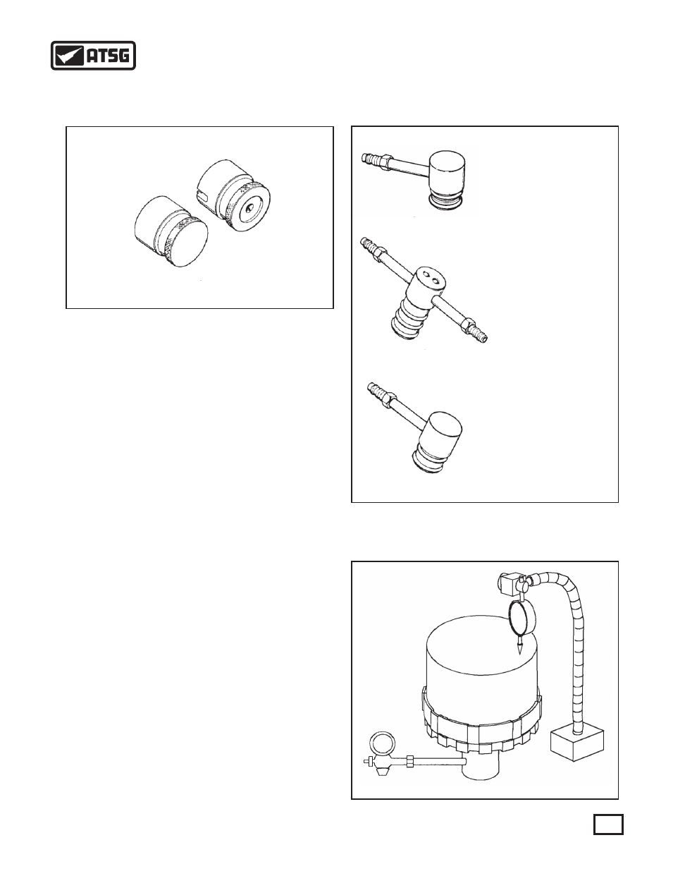
Figure 119

SA91111T-1 TOP WEIGHT

SA91111T-2 BOTTOM WEIGHT

SA9147T 1ST GEAR

AIR CHECK TOOL

SA9109T 2ND & 3RD

AIR CHECK TOOL

SA9110T 4TH

AIR CHECK TOOL

Figure 120

Figure 121

AIR AND CLUTCH CLEARANCE TEST
     1. To perform this test, Saturn's tools are required.
     2. Place both weights (See Figure 119) onto the clutch
         backing plate as shown in Figure 121. Both
         weights must be used in order to achieve an
         accurate reading.
     3. Install the appropriate air check fixture tool to the
         clutch housing (See Figure 120).
         A) 1st clutch drum.........................SA9147T
         B) 2nd & 3rd clutch drum.............SA9109T
         C) 4th clutch drum........................SA9110T
     4. Position a dial indicator with the tip resting on the
         top of the weight (See Figure 121).
     5. Apply regulated air pressure to the clutch piston
         through the air check tool.
         A) 1st clutch piston.........................415 kPa (60 psi)
         B) 2nd, 3rd and 4th clutch pistons..550 kPa (80 psi)
     6. Zero dial indicator. Apply the regulated air pressure
         and measure the piston travel. If end play is not
         within factory specifications, release the pressure
         and change the selective backing plate retaining
         snap ring (See Figure 118 on page 58).
          
         CLUTCH PACK END PLAY
         1st    0.960 - 1.410 mm  (.038" - .055")
         2nd   1.520 - 2.190 mm  (.060" - .086")
         3rd    1.170 - 1.560 mm  (.046" - .061")
         4th    0.910 - 1.180 mm  (.036" - .046") 

59

AUTOMATIC TRANSMISSION SERVICE GROUP

Technical Service Information

1st Drive Gear Hub

to Bearing Thrust Washer

2nd/Rev & 3rd Clutch

Hub Thrust Washer

2nd/Rev Drive Gear

Thrust Washer

1st Clutch Drum Hub

to 1st Clutch Drive Gear

Thrust Washer

IMPORTANT: Chamfer side
goes towards housing and flat
side toward the bearing.

Figure 122

INPUT SHAFT ASSEMBLY AND THRUST WASHER OVERVIEW

First Drive Gear

Second/Reverse 

Drive Gear

Third Drive Gear

Fourth Drive Gear

60

AUTOMATIC TRANSMISSION SERVICE GROUP

Technical Service Information

INPUT SHAFT ASSEMBLY
     1. Prepare the first clutch drum assembly by keying 
         the tabs on the washer with the slots on the hub.
         IMPORTANT: The chamfer side of the washer
         must face the housing (See Figures 122 and 123).
     

2. Install the single sided needle bearing thrust

         washer with the needle bearings facing the washer
         (See Figure 123).
     3. Install the split caged needle bearing onto the first
         clutch drum hub (See Figure 123).
     4. Index the 1st drive gear to the internally splined 
         fiber plates by rotating the gear back and forth
         until the gear bottoms out on the needle bearing
         thrust washer (See Figure 123).
         NOTE: All bearings should be lubed with
         transmission fluid during assembly.
     5. Set the drum aside. Lube and install new rubber O
         ring clutch seals into the grooves on the input shaft
         (See Figure 124).
     6. Using petroleum jelly, secure the 2nd/Rev and 3rd
         clutch hub thrust washer onto the clutch housing.
         The washer goes onto the third gear side of the
         housing. Make sure the slots on the washer line up
         with the tangs on the clutch housing (See Figure
         125).
     7. Using petroleum jelly, secure the double sided
         needle bearing onto the 3rd drive gear with the
         open face towards the thrust washer on the housing
         (See Figure 125).
     8. Secure the caged needle bearing with petroleum
         jelly to the inside race of the 3rd drive gear (See
         Figure 125)
     9. Secure the second double sided needle bearing to
         the 3rd drive gear with the open face towards the
         gear using petroleum jelly (See Figure 125). 

Figure 123

1st Clutch Drum Hub

to 1st Clutch Drive Gear

Thrust Washer

IMPORTANT: Chamfer side
goes towards housing and flat
side toward the bearing.

Figure 124

Figure 125

OPEN 

FACE

OPEN 

FACE

   10. Index the 3rd drive gear to the internally splined
         fiber plates by rotating the gear back and forth
         until the gear bottoms out on the thrust washer
         (See Figure 125).

61

AUTOMATIC TRANSMISSION SERVICE GROUP

Technical Service Information

   11. Support the 2nd/Rev and 3rd clutch drum
         assembly with the 3rd drive gear facing up and that
         the center of the drum is not obstructed (See Figure
         126).
   12. Install the input shaft down through the 3rd drive
         gear and clutch drum assembly previously
         assembled. Be sure that the O rings on the shaft is
         lubricated well with petroleum jelly. Use a twisting
         motion to line up the shaft with the splines in the
         drum assembly. Once the splines are lined up, snap
         the shaft down into position. Be sure that the 3rd
         drive gear fits all the way against the 4th drive gear
         (See Figure 126).
   13. Install the 2nd/Rev drive gear thrust washer. The
         washer has an internal tang that lines up with the
         lube slot on the shaft (See figure 127).
   14. Install the 2nd/Rev needle bearing cage inner race.
         It may be necessary to use a heat gun or a press. If
         a press is used, be sure to support the input shaft
         assembly under the 4th drive gear (See Figure
         127).
   15. Install the double sided needle bearing with the
         open face towards the tanged washer (See Figure
         127).
   16. Install the caged needle bearing (See Figure 127).
   17. Index the 2nd/Rev drive gear to the internally
         splined fiber plates in the drum by rotating the gear
         back and forth until the gear bottoms out on the
         needle bearing thrust washer (See Figure 127).
   18. Secure the single sided needle bearing washer on
         the 2nd/Rev drive gear with petroleum jelly. The
         needle face of the bearing faces the gear (See
         Figure 127).
   19. Install 3 new input shaft sealing rings (Teflon
         Rings) using Saturn's input shaft seal installer kit
         or equivalent (See Figure 128). Saturn's seal

Figure 126

Figure 127

Figure 128

Figure 129

OPEN 

FACE

TM

62

AUTOMATIC TRANSMISSION SERVICE GROUP

Technical Service Information


Content   ..  12  13  14  15   ..