Saturn Transmission. Manual - part 13
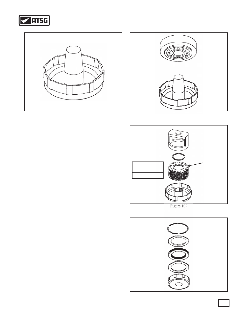
Figure 107
Figure 108
NOTE: Prior to using any of the clutch piston
installation tool, inspect the tool for any nicks or
burrs that could damage the clutch piston seals.
FIRST CLUTCH DRUM ASSEMBLY
1. Place the 1st clutch piston return spring assembly
into the 1st clutch drum. (See note in Figure 109).
Using Saturn's spring compression tool,
SA9146T or equivalent, carefully compress
the spring. With the spring compressed, use a
suitable pair of snap ring pliers and install the
retaining snap ring (See Figure 109).
2. Install the apply plate into the clutch housing with
the fiber side facing up. Install all clutch plates
starting with an internally splined plate first,
alternate plates with the fiber side facing up (See
Figure 110).
NOTE: All fiber plates should be presoaked for
ten minutes in Dexron IIE or Dexron IIIE.
3. Install the clutch backing plate and selective
retaining snap ring (See Figure 110).
4. The clutch clearance in the 1st clutch drum should
measure .038" to .055". The clutch pack clearance
is adjusted with the retaining snap ring. Refer to
figure 118 on page 58 for the different selective
sizes and part numbers.
NOTE: 1991 and early 1992 1st clutch drums
contained one apply plate which measures
approximately .130" in thickness. This apply
plate is externally splined. There is also a total of
three internally splined and two externally
splined fiber plates in the drum. Turn to page 56
for the mid 1992 and up 1st clutch drum
assembly.
Figure 109
Figure 110
55
AUTOMATIC TRANSMISSION SERVICE GROUP
Technical Service Information
1st CLUTCH RETURN
SPRING DIMENSIONS
Wire Diameter
.062"
8
Number of Coils
NOTE
THE NUMBER
"7" STAMPED
IN THE RETAINER
USUALLY
I.D'S THE 1ST
CLUTCH SPRING
ASSEMBLY
NOTE: THE USE OF
THE 2ND, 3RD OR
4TH SPRING RETAINER
IN PLACE OF THE 1ST
SPRING RETAINER
MAY CAUSE DELAYED
ENGAGEMENT IN "D"