Saturn Transmission. Manual - part 10
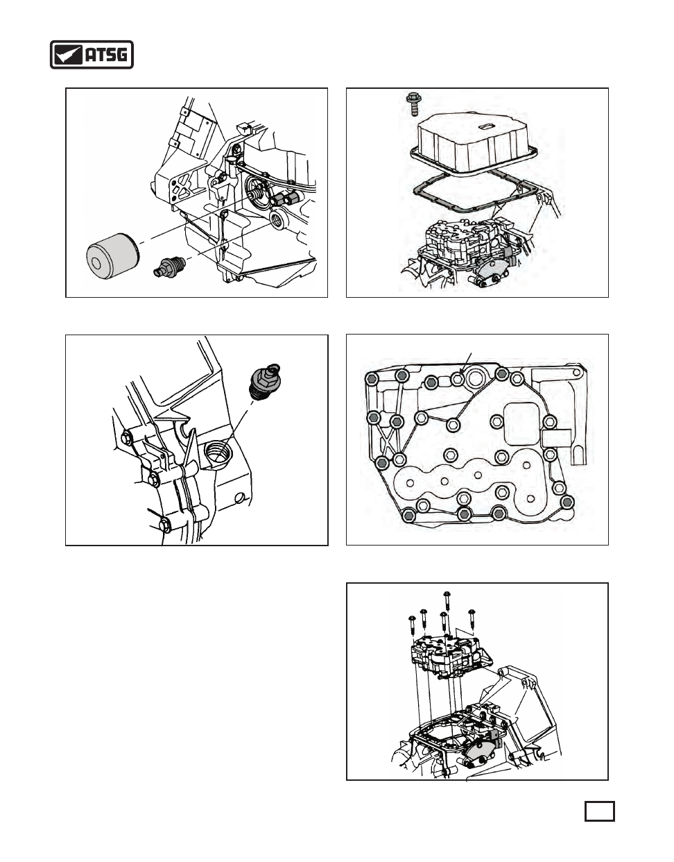
Figure 59
Figure 60
Figure 61
Figure 63
DO NOT REMOVE THIS BOLT
Figure 62
6. Using a 24mm wrench, remove the turbine shaft
speed sensor (See Figure 59).
7. With the same wrench, remove the output shaft
speed sensor (See Figure 60).
8. Remove the thirteen 8mm retaining bolts from the
valve body cover and carefully lift the cover off the
case without damaging the actuator connector (See
Figure 61).
9. To remove the valve body assembly, remove the
eleven outside 8mm bolts highlited in figure 62. Do
not remove the top cnter bolt shown in Figure 62.
10. Once the retaining bolts have been removed, lift the
valve body assembly from the case (See Figure
63).
REMOVE BOLTS INDICATED IN DARK
43
AUTOMATIC TRANSMISSION SERVICE GROUP
Technical Service Information