Saturn Transmission. Manual - part 5


  Index      Saturn     Saturn Transmission - service manual


Search            


Content   ..  3  4  5  6   ..


Saturn Transmission. Manual - part 5


J2

 CONNECTOR

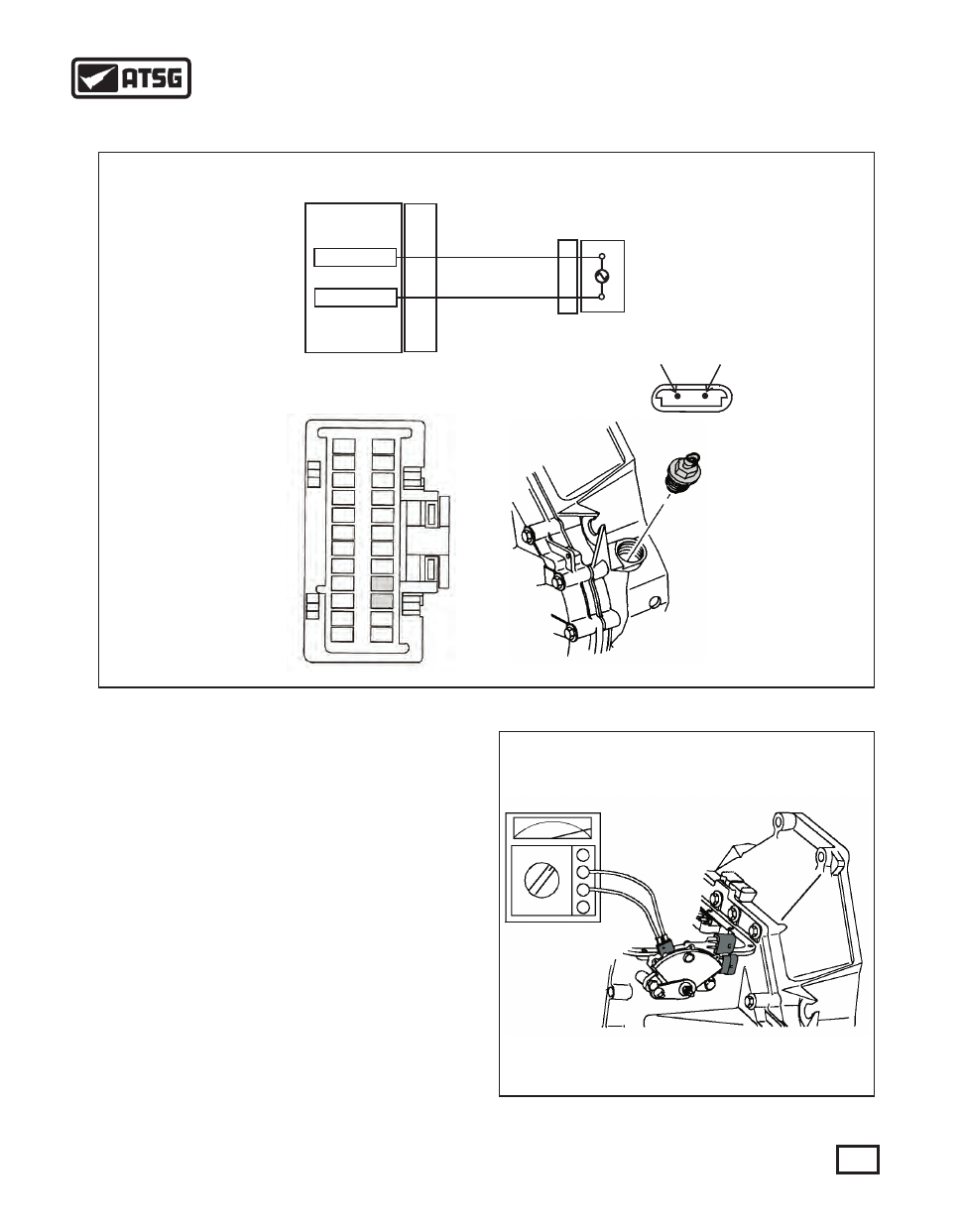
Vehicle Speed Sensor Wiring Diagram

VSS HI

VSS LOW

A10

A9

PCM

J2

Connector

A

B

YELLOW

PURPLE

VEHICLE SPEED

SENSOR

B

A

1
2
3

5

4

6
7
8
9

10
11
12

A

B

VSS

Figure 28

*TCC HOLD CIRCUIT

The TCC Hold Circuit shown in Figure 27 (*5 ohm wire 
circuit) is a 1991 and 1992 model year feature only. The 
amount  of  electrical  current  required  to  energize  an 
actuator  is  greater  than  the  amount  required  to  hold  an 
actuator in position. The Hold Mode is a feature built into 
the PCM that reduces current draw of the TCC actuator 
when TCC is being held on. After TCC is applied a driver 
built into the PCM is opened and an actuator ground path is 
provided  inside  the  PCM  through  the  5  ohm  resistance 
wire.

PATTERN SELECT SWITCH

To adjust the Pattern Select Switch, put the selector lever in 
the  D4  position.  Do  not  start  the  vehicle.  Place  an  ohm 
meter onto the Pattern Select Switch as shown in Figure 29 
(The terminal contacts to be used is in connector 1 shown 
in Figure 27 on page 22). Rotate the switch until the ohm 
meter reads continuity. Once adjusted, secure the Pattern 
Select Switch.

Figure 29

CONT.

23

AUTOMATIC TRANSMISSION SERVICE GROUP

Technical Service Information

Schematic shown

is for vehicles up

to 1994

PATTERN SELECT SWITCH CONTINUED: 
After the Pattern Select Switch has been adjusted, the gear 
selection can be viewed through a hand held scanner to 
ensure that the proper signal is being sent to the PCM. If 
the scanner reveals that the switch is sending an incorrect 
signal  after  an  adjustment,  a  check  can  be  made  on  the 
switch to determine if the switch is defective or the wiring 
is  defective.  Figure  30  below  shows  a  view  of  a  6  pin 
connector on the switch where the check is to be made. The 
bottom pin is terminal A, the next one up is terminal B then 
C, D, E and F. These letters are molded into the connector 
along side each of the pins for easy identification. Figure 
31 illustrates which pins are suppose to be GROUNDED 
in P, R, N, D4, D3 and D2. With the switch mounted to the 
transaxle, place the negative lead of the ohm meter to a 
good known ground. Place the positive lead onto terminal 
A. There should be continuity in P, R and D2 only. Repeat 
the  same  procedure  for  each  pin  utilizing  the  chart  in 
Figure 31 to determine proper grounding sequence.

A

B

C

D

Figure 31

Gear

Select

P

R

N

D4

D3

D2

A           B           C           D

X

X

X

X

X

X

X

X

X

X

X

X

X = Pin Grounded

TRANSAXLE FLUID TEMP. SENSOR

The  transaxle  fluid  temperature  sensor  (TFT)  monitors 
fluid temperature by using a thermistor (sensor) located in 
the  transaxle  pressure  port  near  the  external  filter.  The 
sensor  resistance  will  increase  as  temperature  decreases 
and  decreases  as  the  temperature  increases.  The  PCM 
supplies  a  5  volt  signal  through  the  Tan/White  wire  to 
terminal A on the sensor and monitors the voltage return on 
the Orange/Black wire coming out of terminal B. As the 
resistance goes up, the voltage goes down, as the resistance 
goes down, the voltage return goes up. The voltage value 
on the return signal line is converted to a temperature value 
in  the  PCM.  Most  hand  held  scanners  can  view  the 
temperature values. If the sensor fails, or the wiring circuit 
should  short  or  open,  a  DTC  31  or  32  could  appear. To 
check the operation of the temperature sensor, unplug the 
sensor.  Place  the  positive  lead  to  terminal  A  and  the 
negative lead to terminal B (See Figure 32). Use the chart 
illustrated in Figure 32 for the temperature values and the 
corresponding resistance.

-40
-29
-18

-7

 4

16
27
38
49
60
72
83
94

105
120
140

-40
-20

 0

20
40
60
80

100
120
140
160
180
200
220
248
284

93630
46352
24094

13111

7436
4180
2554
1609
1043

693
456
318
226
165
109

65

C °

F °

RESISTANCE

A

TAN/WHT

B

ORN/BLK

Figure 32

24

AUTOMATIC TRANSMISSION SERVICE GROUP

Technical Service Information

TURBINE SPEED SENSOR

The Turbine Speed Sensor (TSS) is a permanent magnet 
(PM)  generator  mounted  near  the  pressure  filter  on  the 
transaxle  case  (See  Figure  27).  The  PM  generator 
produces a pulsing voltage (AC) whenever turbine shaft 
speed is above 250 rpm. These pulses occur eight times per 
each turbine shaft revolution and is converted to an RPM 
signal inside the PCM. These pulses can be viewed with a 
DVOM set to Hz. If a DVOM is set on  AC volts, voltage 
would increase with speed. If this sensor is checked with 
an ohm setting, the resistance value should be between 800 
to  1600  ohms.  The  Turbine  RPM  signal  can  also  be 
checked and viewed through a hand held scanner. 

VEHICLE SPEED SENSOR
The  Vehicle  Speed  Sensor  (VSS)  is  located  on  the 
transaxle  case  by  the  differential  (See  Figure  28).  This 
sensor  is  also  a  also  a  PM  generator  which  produces  a 
pulsing voltage (AC) whenever the vehicle speed is above 
5 km/h (3 mph). These pulses occur sixteen times per each 
revolution of the differential housing and is converted to 
provide vehicle speed in miles per hour inside the PCM. 
These pulses can be viewed with a DVOM set to Hz. If a 
DVOM is set on AC volts, voltage would increase with 
speed. If this sensor is checked with an ohm setting, the 
resistance value should be between 800 to 1600 ohms. The 
Vehicle  Speed  signal  can  also  be  checked  and  viewed 
through a hand held scanner. 

BRAKE SWITCH
The Brake Switch contains 2 four pin connectors as shown 
in Figure 33. Terminal "B" in connector 1 receives battery 
voltage from the Ignition Run circuit.  When the brake is 
released, this battery voltage is allowed to travel through 
the  switch  and  out  terminal  "C"  in  connector  2.  This 
battery  voltage  is  then  sent  to  the  PCM  in  connector  J3 
terminal E5 (See Figure 25 on page 20). If the transaxle is 
in 2nd gear and engine speed is low, and the brake switch 
opens signalling the PCM that the brakes are applied, the 
PCM unlocks the converter. For 1993 and up this switch 
helps determine if a downshift should occur while going 
down hill. 
The switch can be checked with an ohm meter by placing 
meter leads across terminal B in connector 1 and terminal 
C in connector 2. Continuity should be seen with the brake 
released and go to open as soon as the brake is applied.

A

B

C

D

A

B

C

D

Figure 33

THROTTLE POSITION SENSOR
The Throttle Position Sensor (TPS) is a variable resistor 
that is connected to a 5 volt reference source, a ground, and 
an  input  signal  at  the  PCM  (See  Figure  34).  When  the 
throttle blade is closed, the sensor input voltage will be low 
and increase as the throttle is opened. The TPS is mounted 
on the throttle body facing the firewall and is connected to 
the  throttle  shaft  which  is  controlled  by  accelerator 
movement. If a suspected malfunction occurs, DTC's 21 
and 22 will be stored in the Engine side of the PCM. 
To check the TPS, carefully back probe terminal "B" with 
the negative lead of a volt meter set to DC volts. With the 
positive  lead,  carefully  back  probe  terminal  "C"  (See 
Figure  34).  Turn  the  ignition  on  without  starting  the 
engine. At closed throttle, approximately  0.5 volts should 
be seen. As the throttle increases, the voltage should rise 
smoothly and proportionally. When wide open throttle is 
reached, approximately 4.5 volts should be seen.  

Brake Switch

5V REF

Signal 

Voltage

Ground

PCM

J2-B5

J2-A8

J1-D3

A

B

C

TPS

A =
C =
B =

Gray
Dk Blue
Black

TPS Connector View

Figure 34

Connector 1         Connector 2

Battery
Voltage

Signal wire to 

Connector

J3 pin E5

25

AUTOMATIC TRANSMISSION SERVICE GROUP

Technical Service Information

ENGINE COOLANT TEMP. SENSOR
The  Engine  Coolant  Temperature  Sensor  (ECT)  is  a 
thermistor  located  in  the  lower  coolant  passage  of  the 
engine's cylinder head under the EGR valve. When coolant 
temperature is cold the sensor has a high resistance, as the 
temperature  increases  the  resistance  of  the  sensor 
decreases.  The  PCM  (Connector  J1  terminal  C12) 
provides a 5 volt signal to the coolant sensor (Terminal A). 
The wire coming from terminal B at the sensor is internally 
grounded  in  the  PCM  at  connector  J1  terminal  C3  (See 
Figure 35). The PCM reads the voltage drop on the signal 
line which is calculated and translated to determine engine 
coolant temperature. 

ECT

A

B

J1-C12

J1-C3

Signal

Wire

5V REF

PCM

Figure 35

This ECT sensor circuit could produce DTC's 14, 15 or 17 
depending  upon  the  type  of  failure.  If  the  ECT  sends  a 
temperature  reading  higher  than  140°C  (284°F)  and  the 
engine has only been running just a little over 10 seconds, a 
DTC  14  would  appear.  If  the  engine  has  been  running 
longer than 5 minutes and the temperature remains below -
35°C (-31°F), a DTC 15 will appear. A DTC 17 will set if 
the pull-up resistor inside the PCM switches and there is no 
change in the coolant temperatures signal. The resistance 
check  chart  shown  in  Figure  36  provides  approximate 
ohms values based on temperature. 
NOTE: It is near impossible to check the resistance of 
this sensor while its still in the car. The entrance hole to 
the two pins contained in the sensor is only a ¼ inch in 
diameter  and  the  pins  are  small,  delicate  and  close 
together.  It  is  highly  recommended  that  a  hand  held 
scanner be used to check coolant temperature during 

-40
-29
-18

-7

 4

16
27
38
49
60
72
83
94

105
120
140

-40
-20

 0

20
40
60
80

100
120
140
160
180
200
220
248
284

93630
46352
24094

13111

7436
4180
2554
1609
1043

693
456
318
226
165
109

65

C °

F °

RESISTANCE

A

YELLOW

B

BLACK

Figure 36

any  diagnosis.  The  following  is  an  example  of 
diagnosing the temperature sensor with a scanner: 
1)  DTC  14  =  If  a  high  temperature  reading  exists  at  all 
times, unplug the connector and view the scanner to see if 
the reading went below -35°C (-32°F). If it did, the ECT is 
bad. If it didn't, either the wiring is shorted to ground or the 
PCM is bad. 
2)  DTC  15  =  If  the  temperature  reading  remains  low, 
unplug the temperature sensor and cross the two terminals 
in the connector with a suitable jumper. View the scanner 
to see if the temperature now reads above 130°C (266°F). 
If it did, either the sensor is bad, or the pin cavities are not 
making a tight fit onto the pins. If it didn't, either there is an 
open in the wiring, or the PCM is bad.
3) DTC 17 = PCM is bad.
IMPORTANT:

 The pins in the sensor can be easily bent 

when plugging the connector back on. Be very careful as 
the alignment slots alone do not guide the connector onto 
the pins properly. The part number for the ECT sensor at 
the time of printing is 21020104.

26

AUTOMATIC TRANSMISSION SERVICE GROUP

Technical Service Information


Content   ..  3  4  5  6   ..