Porshe 911 (997). Manual - part 191
Connecting screws
1. Guide in the transmission, and screw in and tighten the fastening
screws.
Location
Explanation
Type
Basic
value
Tolerance
1
Tolerance
2
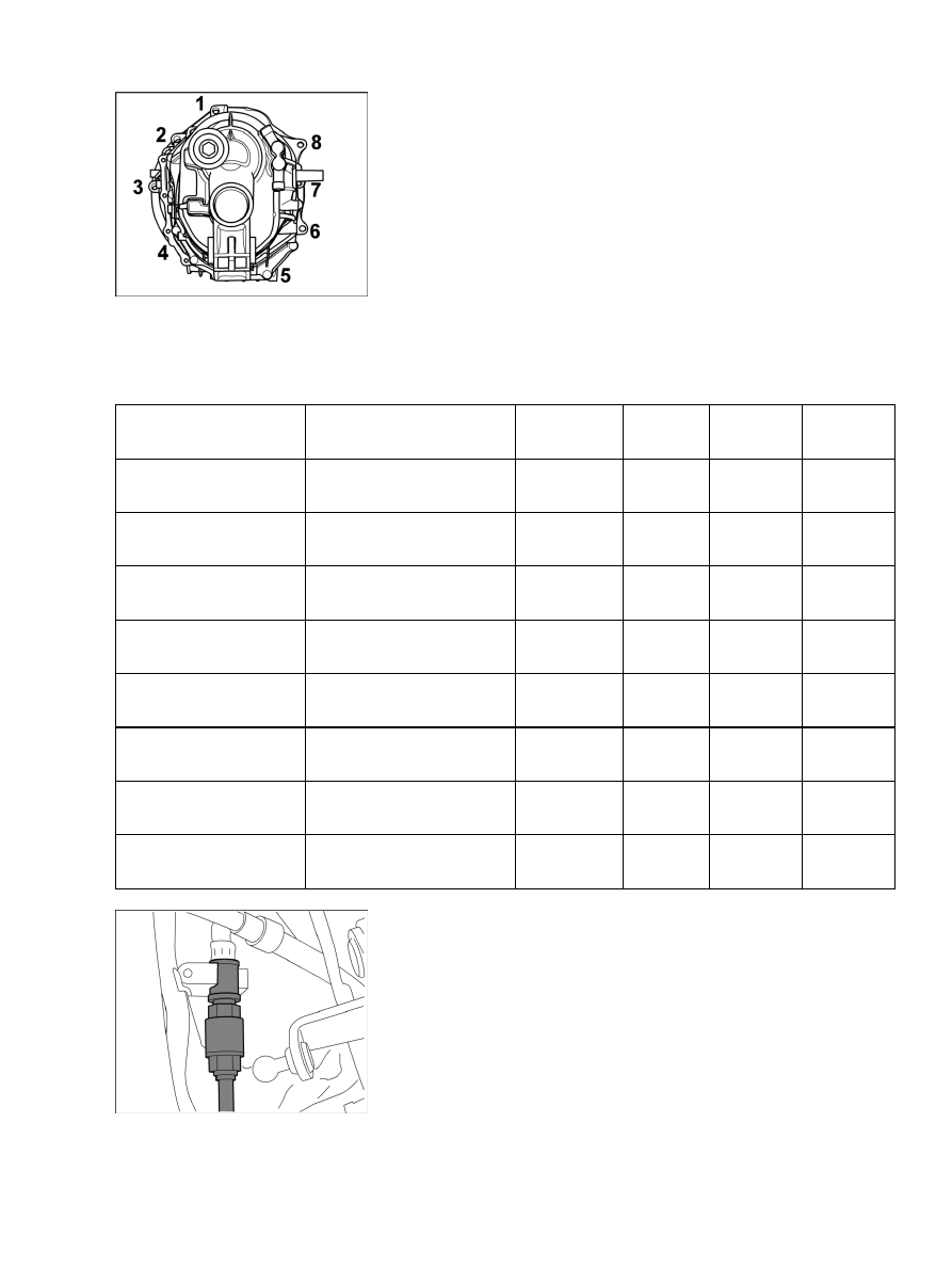
Transmission/engine
connection
Hexagon-head bolt no. 1 in
figure, M12 x 70
Tightening
torque
85 (63
ftlb.) Nm
Transmission/engine
connection
Hexagon-head bolt no. 2 in
figure, M12 x 100
Tightening
torque
85 (63
ftlb.) Nm
Transmission/engine
connection
Hexagon-head bolt no. 3 in
figure, M12 x 100
Tightening
torque
85 (63
ftlb.) Nm
Transmission/engine
connection
Internal serration screw no.
4 in figure, M10 x 50
Tightening
torque
46 (34
ftlb.) Nm
Transmission/engine
connection
Hexagon-head bolt no. 5 in
figure, M10 x 50
Tightening
torque
46 (34
ftlb.) Nm
Transmission/engine
connection
Hexagon-head bolt no. 6 in
figure, M12 x 50
Tightening
torque
85 (63
ftlb.) Nm
Transmission/engine
connection
Hexagon-head bolt no. 7 in
figure, M12 x 70
Tightening
torque
85 (63
ftlb.) Nm
Transmission/engine
connection
Hexagon-head bolt no. 8 in
figure, M12 x 70
Tightening
torque
85 (63
ftlb.) Nm
Clutch line
2. Remove plug from hydraulic line of clutch control and fit the line.
Diagnostic system: reading out fault memory and activating systems
Installing transmission
921