Porshe 911 (997). Manual - part 1064


  Index      Hummer     Porshe 911 997 series - service repair manual 2004-2008 year


Search            


Content   ..  1062  1063  1064  1065   ..


Porshe 911 (997). Manual - part 1064


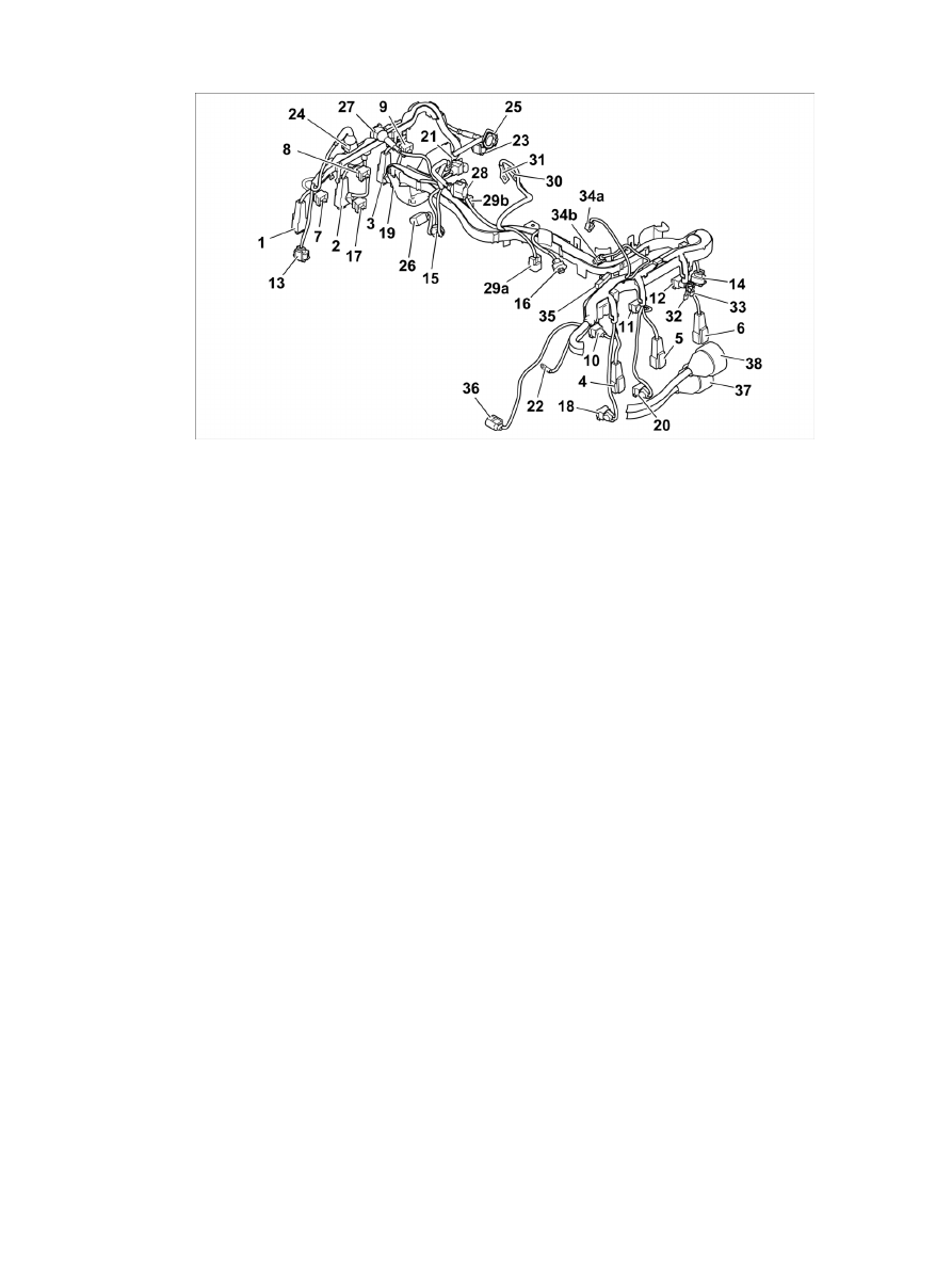
Overview of plugs for engine wire harness

1-3

- Ignition coil plug, cylinder 1 - 3

4-6

- Ignition coil plug, cylinder 4 - 6

7-9

- Fuel injector plug, cylinder 1 - 3

10-12

- Fuel injector plug, cylinder 4 - 6

13

- Camshaft sensor plug, cylinder row 1 - 3

14

- Camshaft sensor plug, cylinder row 4 - 6

15

- Knock sensor connector, cylinder row 1 - 3

16

- Knock sensor connector, cylinder row 4 - 6

17

- Solenoid hydraulic-valve plug (camshaft timing), cylinder row 1 - 3

18

- Solenoid hydraulic-valve plug (camshaft timing), cylinder row 4 - 6

19

- Solenoid hydraulic-valve plug (valve lift control), cylinder row 1 - 3

20

- Solenoid hydraulic-valve plug (valve lift control), cylinder row 4 - 6

21

- Ground strap

22

- Ground strap

23

- Speed sender

24

- Connector for intake-pipe change-over switch

25

- Secondary air blower plug

26

- Generator plug

27

- Tank vent connector

28

- Throttle valve connector

29A

- Oil level sensor connector, M9605

29B

- Oil level sensor connector, M9701

30

- Starter lead for terminal 30

31

- Starter lead for terminal 50

32-33

- Pressure sensor plug

34A

- Engine-temperature sensor connector, M9605

34B

- Engine-temperature sensor connector, M9701

Diagnostic system: reading out fault memory and activating systems

Installing wire harness for engine

4413

35

- A/C compressor connector

36

- Water-temperature sensor connector

37-38

- Plug connections for engine wire harness to rear wire harness

1. Lay out wire harness for engine.

Installing cable duct

2. Install cable duct.

2.1. Clip in cable duct -Arrows- and secure with the fastening screws. → Tightening torque: 10 (7.5

ftlb.) Nm

Clipping in starter lead at cable duct

3. Clip in starter lead.

3.1. Clip in starter lead at cable duct

-Arrows-

 .

Clipping in cable duct at left and right

4. Clip in cable duct at the left and

right.

4.1. Position and clip in cable duct on the left and right at the fuel distributor pipes -Arrows- .

Diagnostic system: reading out fault memory and activating systems

Installing wire harness for engine

4414

Round connectors for engine wire harness

5. Push plug connection for engine wire harness to rear wire harness -37 and 38- together. → 100119

Removing and installing engine - section on "Installing"

5.1. Connect engine wire harness at the two plug connections and lock it by turning the bayonet locks

clockwise.

Engine wire harness attachment

5.2. Fit new tie-wrap -Arrow- .

Attaching connector on water temperature sensor

6. Attach connector on water temperature sensor -36- .

6.1. Plug in connector on water temperature sensor -36- ( -Arrow A- ) until it engages firmly.

6.2. Insert wire into the holder and close holder -Arrow

B-

 .

7. Press plug connection for compressor -35- together until it is felt to engage. → 873419 Removing

and installing compressor - section on "Installing"

8. Plug in connector on engine temperature sensor -34- until it engages firmly.

9. Connect plugs on pressure sensor -32 and 33- .

10.

Diagnostic system: reading out fault memory and activating systems

Installing wire harness for engine

4415

Position starter lead for terminal 50 -31- and secure with fastening nut. → Tightening torque: 6.5 (5.0
ftlb.) Nm

 → 276019 Removing and installing starter - section on "Installing"

11. Plug in connector on oil level sensor -29- until it engages securely.

12. Plug in connector on tank vent -27- until the securing clip engages securely.

13. Connect plug on secondary air blower -25- until it engages firmly. → 266519 Removing and

installing secondary air pump - section on "Installing"

14. Plug in connector on intake-pipe change-over switch -24- until the securing clip engages securely.

Connecting plug connection on speed sender

15. Screw down ground straps -21- and connect plug connection on speed sender -23- .

15.1. Position ground straps -21- and screw down the fastening screw. → Tightening torque: 10 (7.5 ftlb.)

Nm

15.2. Push the plug connection -23- together until it is felt to engage.

15.3. Push plug connection -23- into holder.

Screwing down ground straps on engine

16. Screw down ground straps -22- .

16.1. Position ground straps -22- and screw down the fastening screw. → Tightening torque: 10 (7.5 ftlb.)

Nm

17. Connect plugs on the two solenoid hydraulic valves (valve lift control) -19 and 20- until they click

into place. → 155519 Removing and installing solenoid hydraulic valve (valve lift control) - section
on "Installing"

18. Connect plugs on the two solenoid hydraulic valves (camshaft timing) -17 and 18- until they click into

place. → 153719 Removing and installing solenoid hydraulic valve (camshaft timing) - section on

Diagnostic system: reading out fault memory and activating systems

Installing wire harness for engine

4416


Content   ..  1062  1063  1064  1065   ..