Porshe 911 (997). Manual - part 1060


  Index      Hummer     Porshe 911 997 series - service repair manual 2004-2008 year


Search            


Content   ..  1058  1059  1060  1061   ..


Porshe 911 (997). Manual - part 1060


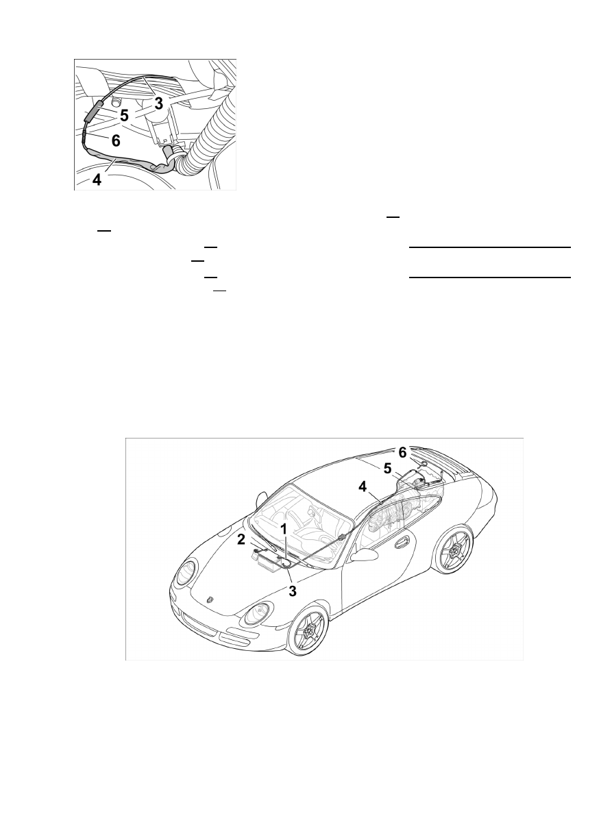
Crimping the positive cable

3.2. Strip insulation off original positive cable of main wire harness -3- and push on the shrink-fit hose

-5-

 .

3.3. Crimp crimping sleeve -6- using the hand crimping pliers from the repair kit for harnesses NR.155-1

to the positive cable -3- .

3.4. Crimp crimping sleeve -6- using the hand crimping pliers from the repair kit for harnesses NR.155-1

to the new positive cable -4- . Check the crimp connection carefully.

3.5. Slide the shrink-fit hose over the crimp connection and carefully shrink it using the hot-air blower with

special nozzle

 (recommended accessories for the repair kit for harnesses) so that it is watertight.

3.6. Tie positive cable to the main wire harness with adhesive tape.

Install B+ line from power distributor to transmission connection point

Installation Location:

Installation position of wire harness for battery wiring

3

- B+ line from power distributor to transmission connection point

4

- Connection point of B+ box on transmission

Diagnostic system: reading out fault memory and activating systems

Install B+ line from power distributor to transmission connection point

4397

Installing B+ line

1. Install B+ line -3- .

1.1. Lay B+ line to transmission and push into the vehicle interior -Arrow A- .

1.2. Press B+ line into the grommet -Arrow

B-

 .

1.3. Fit grommet -Arrow C- .

Note

For vehicles with manual transmission.

Clip B+ line onto transmission bracket.

2. Clip B+ line -3- onto transmission bracket.

2.1. Insert B+ line into holder -Arrow A- and close holder -Arrow

B-

Note

For vehicles with automatic transmission.

Diagnostic system: reading out fault memory and activating systems

Install B+ line from power distributor to transmission connection point

4398

Fastening guide tube of B+ line

3. Screw down guide tube of B+ line -3- on the body.

3.1. Position guide tube of B+ line on the body and screw down with fastening screw and fastening

nut. → Tightening torque: 10 (7.5 ftlb.) Nm → Tightening torque: 10 (7.5 ftlb.) Nm

Note

For vehicles with automatic transmission.

Transmission support

4. Install transmission

support.

4.1. Position the transmission support and secure with the four fastening screws and the two fastening

nuts. → Tightening torque: 65 (48 ftlb.) Nm

4.2. Lower transmission jack WE1082 and remove from under the

vehicle.

Diagnostic system: reading out fault memory and activating systems

Install B+ line from power distributor to transmission connection point

4399

Screw down B+ line at box for B+ line.

5. Screw down B+ line -3- at box for B+ line -4- .

5.1. Insert B+ line into the box and tighten with the fastening nut -Arrow A- . → Tightening torque:

23 (17 ftlb.) Nm

5.2. Close box for B+ line on transmission -Arrow B- .

Fastening of B+ line at centre tunnel

6. Fasten B+ lead -3- at centre tunnel.

6.1. Push B+ line under the carpet in the direction of travel.

6.2. Insert B+ line into the two holders

-arrows-

 .

Fastening of B+ line at unit carrier.

7. Clip in B+ line -3- at unit carrier.

7.1. Push B+ line through the unit carrier and across the footwell air vent.

7.2. Clip in B+ line -arrow- at unit carrier with the retaining

clip.

Diagnostic system: reading out fault memory and activating systems

Install B+ line from power distributor to transmission connection point

4400


Content   ..  1058  1059  1060  1061   ..