Porshe 911 (997). Manual - part 1022


  Index      Hummer     Porshe 911 997 series - service repair manual 2004-2008 year


Search            


Content   ..  1020  1021  1022  1023   ..


Porshe 911 (997). Manual - part 1022


Removing main wire harness

Removing main wire harness

ATTENTION

Damage caused by improper handling of main wire harness.

→ The main wire harness contains all airbag lines, antenna lines and optical waveguides.

→ The main wire harness must therefore not be cut for major repair work and must be replaced complete.

→ If individual wires are damaged, these must be "shut down" (disconnect wires, remove plug-in contacts

from plug connections, etc.) and replaced by installing new wires. Lay the new wires along the main wire
harness and tie them to it.

Note

Depending on the equipment I No., the installation positions of the audio components in the front luggage
compartment differ.

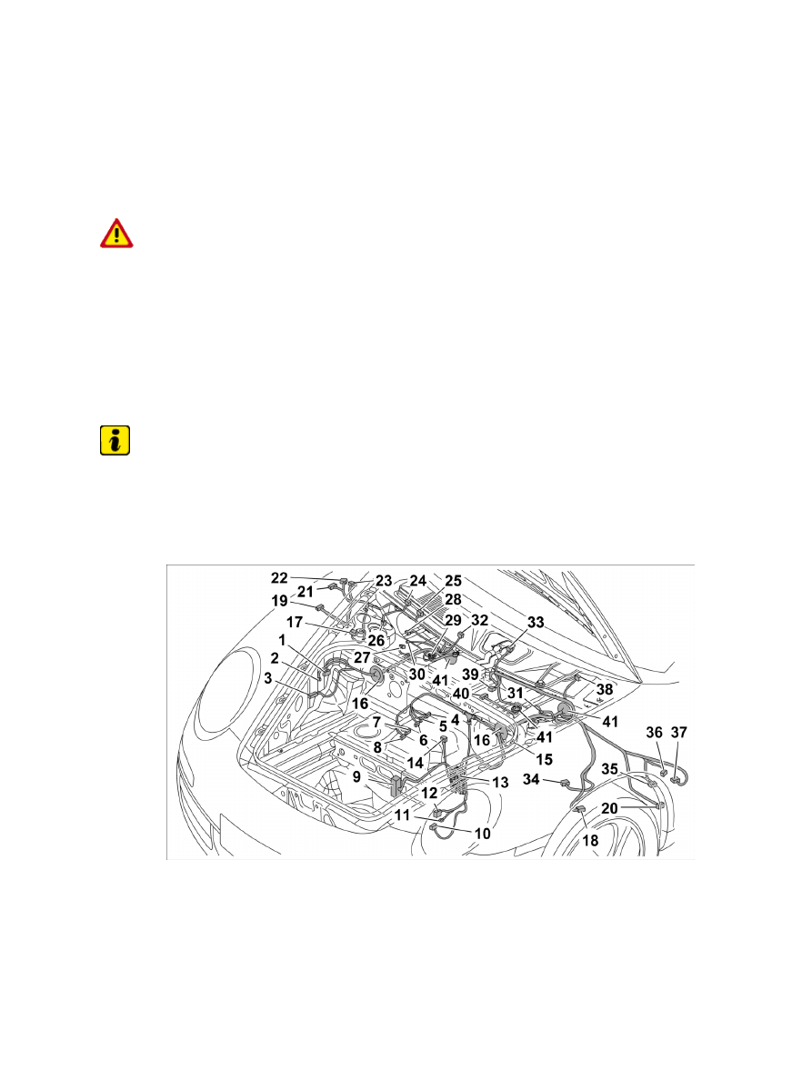
Installation Location:

Overview of connectors for front main wire harness, shown on the 911

1

- Plug connection between main wire harness and front-end wire harness right

2

- Fuse box for fan

3

- Connector for front-end control unit

4-6

- Connector for navigation unit

7-8

- Connector for CD changer

Diagnostic system: reading out fault memory and activating systems

 Removing main wire harness

4245

9

- Connector for loudspeaker amplifier

10

- Connector for luggage compartment light

11

- Ground point

12

- Plug connection between main wire harness and front-end wire harness left

13

- Connector for hydraulic unit

14

- Connector for brake fluid sender

15

- Connector for tyre pressure monitoring system control unit

16

- Grommet

17-18

- Plug connection for ABS wire harness, front left and right

19-20

- Connector for tyre pressure monitoring system antenna, left and right

21

- Connector for filler flap switching element

22

- Connector for tank filler neck

23

- Connector for rod antenna

24

- Connector for GPS antenna

25

- Connector for radio antenna

26

- Connector for vertical sensor

27

- Connector for pressure switch

28

- Connector for alarm siren

29

- B+ line to power distributor

30-31

- Plug connection for PASM, front left and right

32-33

- Connector for windscreen washer system spray nozzle, left and right

34

- Connector for headlight beam adjustment angle sensor

35

- Connector for fluid level indicator sender

36

- Connector for windscreen washer system pump

37

- Connector for headlight washer pump

38

- Connector for wiper motor

39

- Connector for alarm horn

40

- Connector for fuel level sensor

41

- Grommet

Disconnecting plug connection between front-end wire harness and main wire harness, right

1. Disconnect plug connection between main wire harness and front-end wire harness, right -1- .

1.1. Release plug connection between front-end wire harness and main wire harness, right -Arrow a-

Diagnostic system: reading out fault memory and activating systems

Removing main wire harness

4246

and disconnect -Arrow B- .

1.2. Turn socket 90° clockwise and remove.

Pulling off connector on fuse box for fan

2. Pull off connector on fuse box for fan -2- .

2.1. Unclip fuse box for fan -Arrow A- and lift up and off -Arrow B- .

2.2. Release lid -arrows- and open -Arrow

C-

 .

2.3. Pull off connector on fuse box for fan -Arrow D- .

Loosening ground point

3. Loosen ground point left -11- .

3.1. Screw off fastening nut and remove ground straps.

4. Release plug connection between main wire harness and front-end wire harness, left -12- and

disconnect. Unclip connector socket.

5. Release connector on hydraulic unit -13- and pull it off. → 453019 21 Removing and installing

hydraulic unit - chapter on "Removing"

6. Release connector on brake fluid sender -14- and pull it off.

7. Release connector for tyre pressure monitoring system control unit -15- and pull it off. → 443419

Removing and installing control unit for tyre pressure monitoring system - chapter on "Removing"

Diagnostic system: reading out fault memory and activating systems

Removing main wire harness

4247

Unclipping wire harness

8. Unclip wire harness for front end control unit -arrow- .

Unclipping wire harness to loudspeaker amplifier

9. Unclip wire harness to loudspeaker amplifier -Arrows A- and remove adhesive tape -Arrow B- .

Unclipping wire harness to CD changer/navigation unit

10. Unclip wire harness to CD changer/navigation unit -arrows- .

11. Remove grommets -16- left and right.

12. Pull through main wire harness in direction of plenum

panel.

13. Disconnect and release ABS wire harness front left and right -17 and 18- . → 976555 Replacing ABS

wire harness - chapter on "Removing" [997110 997111 997120 997121 997310 997311 997320
997321]→ 976555 Replacing ABS wire harness - chapter on "Removing" [997410 997411 997430
997431 997610 997611 997620 997621]

Diagnostic system: reading out fault memory and activating systems

Removing main wire harness

4248


Content   ..  1020  1021  1022  1023   ..