Porshe 911 (997). Manual - part 88


  Index      Hummer     Porshe 911 997 series - service repair manual 2004-2008 year


Search            


Content   ..  86  87  88  89   ..


Porshe 911 (997). Manual - part 88


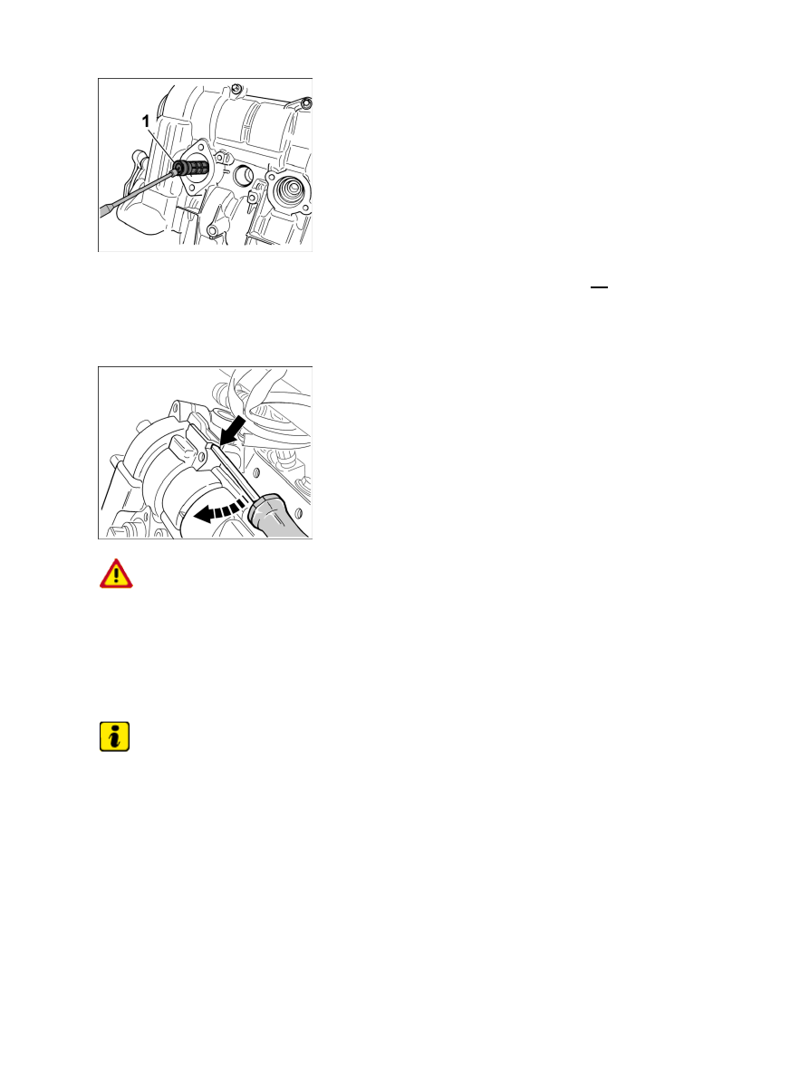
Oil strainer hydraulic valve NVS

5. If the solenoid hydraulic valve is removed for camshaft timing, the oil strainer -1- must be

checked for damage and contamination, and replaced if necessary.

6. Remove oil suction pump. Unscrew four M6 x 20 Torx screws (micro-self-locking), remove oil

suction pump, replace O-ring and screws.

Lifting cylinder head cover from above

ATTENTION

Damage when levering off the cylinder head cover

Cast lugs could break.

• 

→ Perform work steps carefully and gently.

Note

The coated screws for the bearing surfaces of the camshaft in the cylinder head cover must be replaced when
installing.

7. Remove the cylinder head cover . Unscrew 20 M6 x 30 Torx screws from the cylinder head cover. To

loosen the cylinder head cover, raise the cover carefully at the two protruding cast edges with a screw
driver or mounting lever. Remove cylinder head cover.

Diagnostic system: reading out fault memory and activating systems

Removing cylinder head cover - engine removed

509

Lifting cylinder head cover from below

8. Remove the plastic cap.

Note

Make sure that it is cleaned thoroughly and that residual sealing compound is removed completely. Even the
smallest particles can block up oil bores.

9. Clean the sealing faces on the cylinder head cover and cylinder head thoroughly (use brass - or

nylon brush, a clean and lint-free cloth soaked in acetone). All residual sealing compound in the
cylinder head and on the cover must be removed before assembling.

–  Loosen ground cable on the cylinder head, to do this, unscrew on M8 Torx screw and remove the

cable.

–  Unplug two cable plugs for the oil pressure

switch.

–  A tandem pump is installed on side 4-6 instead of the oil suction pump. Pull off the vacuum line on the

pump. Replace O-rings and micro-self-locking screws.

Solenoid hydraulic valve, valve lift control

–  Because of the small distance to the exhaust manifold, the valve lift control valve must be removed, so

that the cover can be removed and installed without difficulty. → 155519 Removing and installing solenoid
hydraulic valve, valve lift control - chapter on "Removing". Pay attention to the spring element.

Installing cylinder head cover - engine removed

Diagnostic system: reading out fault memory and activating systems

 Installing cylinder head cover - engine removed

510

Installing cylinder head cover - engine removed

ATTENTION

Risk of damage due to particles of dirt.

Oil bores/oil ducts can become blocked up.

• 

→ When working on the engine, absolute cleanliness is essential.

→ Lay removed engine parts on a clean base and cover them without fail.

→ Use the cover for dust protection when fitting the engine NR.165 on the engine assembly support.

Note

The coated screws for the bearing surfaces of the camshaft in the cylinder head cover must be replaced when
installing.

Spark plug slot seals and solenoid hydraulic valves

1. Insert three new seals for the spark-plug

recesses.

Only the following sealants may be used to seal the cylinder head cover:

"Drei Bond" silicone - type 1209

• 

Loctite 5900

• 

Sealant application cylinder head cover

Diagnostic system: reading out fault memory and activating systems

Installing cylinder head cover - engine removed

511

2. Prepare cylinder head cover for assembly. Apply a thin bead of sealant on the cylinder head cover

(not higher than 1.5 mm). → Sealant application cylinder head cover

Screws for camshaft bearing surface

3. Coated screws on the camshaft bearing surfaces -1- must be replaced.

4. Place the cylinder head cover carefully onto the cylinder head. The bead of sealing compound must not be

wiped off or interrupted.

Tightening sequence, cylinder head cover

5. Position 20 Torx screws (eight of these should be new, coated screws) on the cylinder head cover and

tighten according to the specified tightening sequence. Only lightly screw in the two screws in the area of
the oil suction pump/tandem pump. They will be tightened after the pump is assembled. → Tightening
torque: 9.5 ftlb.

 → Tightening sequence, cylinder head cover

6. Position a new cap ø 45 mm (brown) on the bore of the intake camshaft on the pulley side and tap it

gently into place with a plastic hammer (dry mount).

7. Insert two new caps (green) into the small bores on the clutch side. Tap it in with a plastic hammer

(dry mount).

Tandem pump side 4 -6

Note

Replace the O-ring on the oil suction pump (tandem pump).

8.

Diagnostic system: reading out fault memory and activating systems

Installing cylinder head cover - engine removed

512


Content   ..  86  87  88  89   ..