Porshe 911 (997). Manual - part 66
adjusting gauge
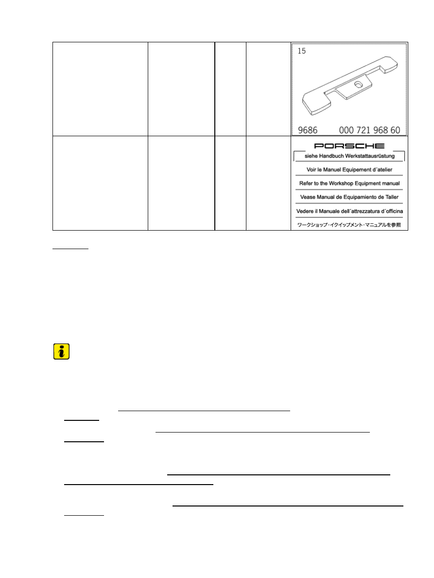
special tool
9686
cover for dust protection
when fitting the engine
commercially
available tool
NR.165
Preliminary work for bearing cover for intermediate shaft
Preliminary work for bearing cover for intermediate shaft
Note
Note the work instructions for disconnecting and reconnecting the battery.
•
1. Disconnect the battery → 271000 Work instructions after disconnecting the battery.
2. Drain engine oil → 170155 Engine oil and oil filter change - section on
3. Remove air cleaner housing → 242519 Removing and installing air cleaner housing - section on
Tiptronic transmission:
4. Remove engine → 101019 21 Removing and installing engine - section on "Removing".
5. Remove Tiptronic transmission → 373527 Removing and refitting automatic transmission - section on
"Removing" [997120 997121 997320 997321]→ 373527 A3 Removing and refitting automatic
transmission - section on "Removing" [997430 997431 997620 997621].
Manual transmission:
Diagnostic system: reading out fault memory and activating systems
Tools
421