Porshe 911 (997). Manual - part 62


  Index      Hummer     Porshe 911 997 series - service repair manual 2004-2008 year


Search            


Content   ..  60  61  62  63   ..


Porshe 911 (997). Manual - part 62


Installation position of housing

Note

Do not interchange the thrust bearings of the inlet and exhaust camshafts during assembly; observe
identification markings.

• 

29. Insert three thrust bearings and one housing -arrows- for the bearing sleeve of the camshafts together

with the guide rail for the timing chain.

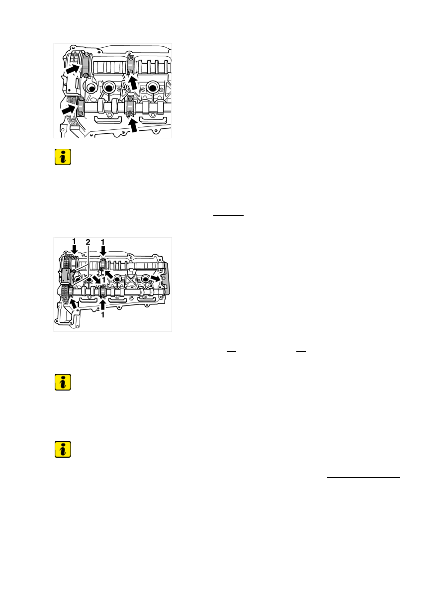
Position of housing screws

30. Insert eight housing screws (Torx): six M6 x 35 -1- and two M6 x 40 -2- for camshaft bearing and guide

rail. Tighten screws evenly and just finger-tight.

Timing for side 1 - 3

Note

Position crankshaft above the pulley or vibration balancer before final adjustment of the timing to the
TDC marking.

• 

Note

Before final tightening (torque angle) of the central screw, the special tool adjusting gauge 9686
must be removed.

• 

31. Final timing adjustment for cylinder bank 1 - 3 is analogous to that for cylinder bank 4 - 6. ;

Diagnostic system: reading out fault memory and activating systems

Installing camshafts, adjusting timing - engine removed

405

Chain tensioner, cylinder 1 - 3

32. Fit chain tensioner for side 1 - 3 (hexagon a/f 32) before turning crankshaft to the TDC mark. Fit

chain tensioner with new sealing ring and tighten. → Tightening torque: 59 ftlb.

After adjusting the timing, this should be re-checked.

Slot position of camshafts at overlap

33. Turn the engine 360° at the crankshaft and fix at the TDC mark. Check camshaft position of

cylinder bank 4 - 6 using the adjusting gauge 9686. Then turn a further 360° and check the
camshaft position of cylinder bank 1 - 3.

Subsequent work for installing camshafts

Subsequent work for installing camshafts

Diagnostic system: reading out fault memory and activating systems

 Subsequent work for installing camshafts

406

Gaskets for spark plug recess and solenoid hydraulic valves

1. Insert solenoid hydraulic valves and new gaskets for the spark-plug recesses. Fit new O-rings into both

solenoid hydraulic valves and insert into the bores in the cylinder head. Grease O-rings with Optimol
MP3. → 153719 Removing and installing solenoid hydraulic valve NVS - chapter on "installing" and
→ 155519 Removing and installing solenoid hydraulic valve VHS - chapter on "installing".

2. Install cylinder head cover → 159119 Removing and installing cylinder head cover - chapter on

"installing".

3. Fit oil suction pump (1 - 3) and tandem pump (4 - 6) with new, micro-self-locking Torx screws M6.

Replace O-rings and grease with Optimol MP3. → Tightening torque: 7.5 ftlb.

4. Fit new plastic cap dry on cylinder head. Tap in with a plastic

hammer.

5. Fit ground strap to cylinder head 4 - 6 with Torx screw M8 x 20 and tighten. → Tightening torque: 17

ftlb.

6. Insert each ignition coil into its spark plug recess, fit two M6 x 25 Torx socket screws and tighten. →

Tightening torque: 7.5 ftlb.

7. Fit retainer plates and holders for the solenoid hydraulic valves. → 153719 Removing and installing

solenoid hydraulic valve NVS - chapter on "installing" and → 155519 Removing and installing
solenoid hydraulic valve VHS - chapter on "installing". → Tightening torque: 7.5 ftlb.

8. Fit holder for rear muffler. Fit and tighten two Torx screws M8 x 30 intake side and two Torx

screws M8 x 25 exhaust side. Fit cable plugs for ignition coils and solenoid hydraulic valves, fixing
cable in the sheetmetal clips. → Tightening torque: 17 ftlb.

9. Fit and tighten cover plate with two Torx screws M6 x 16. → Tightening torque: 7.5 ftlb.

10. Connect two cable plugs to the oil temperature switch for cylinder bank 4 -

6..

997120, 997121, 997320, 997321, 997620, 997621

WARNUNG

Gefahr des Verlusts der Text-Bild-Zuordnung beim Ausdruck.

Aus technischen Gründen kann derzeit nicht ausgeschlossen werden, dass trotz
einwandfreier Darstellung auf dem Bildschirm beim Ausdruck der
Zusammenhang von Text und zugehörigem Bild verloren geht.

• 

Wird der Fehler nicht bemerkt, besteht die Gefahr, daß Arbeiten nicht korrekt
durchgeführt werden und es dadurch zu Personen- und Sachschäden kommt.

• 

→ Vergleichen Sie deshalb nach dem Druckvorgang unbedingt die Ausdrucke mit der
Bildschirmdarstellung. Korrigieren Sie die Ausdrucke im Fehlerfall so, daß der Inhalt der
Bildschirmdarstellung zutreffend wiedergegeben wird.

WARNING

Diagnostic system: reading out fault memory and activating systems

Subsequent work for installing camshafts

407

Danger of losing text-figure correspondence when printing out.

For technical reasons, it can currently not be ruled out that the correspondence
between text and associated figure can be lost when it is printed out, even though
the display on the screen is correct.

• 

If the fault is not noticed, there is the danger that work will not be performed
correctly which can cause injury and damage.

• 

→ Therefore, always compare printouts with the screen display after printing them out. Correct
the printouts if they are faulty so that the content of the screen display matches that on the
printouts.

AVERTISSEMENT

Risque de perte de la correspondance texte-illustration lors de l'impression papier.

Pour des raisons techniques, il ne peut pas être exclu à l'heure actuelle que, même
en cas d'affichage correct à l'écran, la correspondance entre le texte et l'illustration
puisse être erronée sur l'impression papier.

• 

Si l'erreur passe inaperçue, on court le risque d'exécuter certaines opérations de
manière incorrecte pouvant conduire à des dommages corporels et matériels.

• 

→ Comparez impérativement pour cette raison les impressions papier avec l'affichage à l'écran.
Corrigez-les en cas d'erreur de manière à reproduire correctement l'affichage à l'écran.

ATTENZIONE

Pericolo di perdita dell'abbinamento testo-immagine nella stampa.

Per motivi tecnici non è escluso che, nonostante la rappresentazione sullo schermo
risulti perfetta, durante la stampa venga persa la corrispondenza fra testo e
relativa immagine.

• 

Se tale difetto non viene rilevato vi è il pericolo che i lavori non siano eseguiti
correttamente; ciò può avere come conseguenza lesioni e danneggiamenti.

• 

→ Per questo motivo, dopo la stampa è assolutamente necessario confrontare le stampe con la
rappresentazione sullo schermo. In caso di errore si prega di correggere le stampe, così da
garantire la riproduzione esatta della rappresentazione sullo schermo.

ADVERTENCIA

Al imprimir se corre el riesgo de perder la correcta asignación de las figuras al texto.

Por motivos técnicos, por el momento no se puede descartar que, aun siendo
correcta la imagen que aparezca en la pantalla, al imprimir se pierda la
correlación entre el texto y la figura correspondiente.

• 

Si este error pasara desapercibido, existe el riesgo de que los trabajos no se
ejecuten de forma correcta y, por tanto, se produzcan daños personales y
materiales.

• 

Diagnostic system: reading out fault memory and activating systems

Subsequent work for installing camshafts

408


Content   ..  60  61  62  63   ..