Porshe 911 (997). Manual - part 26


  Index      Hummer     Porshe 911 997 series - service repair manual 2004-2008 year


Search            


Content   ..  24  25  26  27   ..


Porshe 911 (997). Manual - part 26


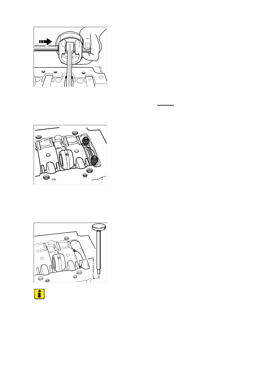
Removing piston pins

10. Lever off the front piston-pin circlips of marked pistons 4-6 (from the viewpoint of the drive belt

side) using a small screwdriver, push out the piston pin -arrow- and remove the pistons one by
one. Assign the piston pins again to the appropriate pistons.

Removing pistons and connecting rods, side 1-3

Connecting rod bolts

11. Remove marked pistons 1-3, including connecting rods. To do this, turn the crankshaft on the

belt pulley/vibration balancer until the respective connecting rod bearing cap stands upwards.
Undo and remove the connecting rod bolts (twelve-edged socket wrench insert a/f 14), remove
connecting rod bearing cap.

Removing connecting rod using plastic mandrel (shop-made)

Note

Join connecting rod and connecting rod bearing cap together again immediately after removal.

• 

Connecting rod bolts must be replaced.

• 

12. Carefully press connecting rod and pistons downwards out of crankcase half 1-3 using a

Diagnostic system: reading out fault memory and activating systems

Removing pistons

261

shop-made plastic mandrel. Allocate a connecting rod cap immediately to the relevant connecting
rod and screw on loosely. Pay attention to the bearing shells.

13. Unscrew fastening screw for belt pulley/vibration balancer and remove washer or damper. In the case of

the vibration balancer, pay attention to the friction plate.

14. To remove connecting rod 4-6, remove the gear carrier; see → 134819 Removing and installing crankshaft

- "Preliminary work" section.

Disassembling pistons/connecting rods, cylinder 1-3

Disassembling pistons/connecting rods, cylinder 1-3

Note

When removing pistons, the piston-pin circlip always remains in the piston, which is installed opposite the
large assembly bore (no chamfer) for the piston pin.

1. Remove piston/connecting rod unit. To do this, clamp the connecting rod to a vice with aluminium jaws,

for example.

Removing/installing piston rings

ATTENTION

Over-extension of piston rings

Damage or breakage

• 

→ Using the piston ring pliers, spread open the piston rings only far enough so that the rings can be

installed or removed (without scratching the piston).

2. Remove piston ring groove 1 and groove 2 separately using a piston ring pliers Gr. 1 NR.58. Remove

piston ring groove 1 first. The piston rings must not be overstretched.

3. The three-piece oil scraper ring can be removed by hand. First, carefully remove both rings, then remove

the springs.

Diagnostic system: reading out fault memory and activating systems

 Disassembling pistons/connecting rods, cylinder 1-3

262

Piston assembly device 9597

4. Insert piston/connecting rod unit into the retaining device 9597 in such a way that the twist lock in the

second piston ring groove faces the observer.

Removing piston pin circlip

5. Carefully press out piston-pin circlip with a screwdriver; while doing so, place a cloth over the

piston so that the circlip does not pop out.

Pressing out piston pin

6. Turn piston/connecting rod unit through 180° on the assembly device and press out piston pin with the

plunger special tool assembly tool 9500.

7. Repeat steps for removing pistons/connecting rods on cylinders 2 and 3.

Assembling pistons/connecting rods, cylinder 1-3

Diagnostic system: reading out fault memory and activating systems

Disassembling pistons/connecting rods, cylinder 1-3

263

Assembling pistons/connecting rods, cylinder 1-3

Note

When removing pistons, the piston-pin circlip always remains in the piston, which is installed opposite the
large assembly bore (no chamfer) for the piston pin.

Note

The lug of the piston-pin circlip must always be touching the contact surface facing the oil piston shank.

Piston assembly device 9597

Special tool retaining device 9597 with spacer ring 9597/1.

Piston pin assembly bore

1. Insert the piston (without piston rings) into retaining device 9597 so that the deep assembly bore for the

piston pin in the piston is facing the observer and the remaining circlip is located underneath (check: twist
lock of piston ring, second groove, is also pointing towards the observer -arrow- , arrow opposite piston
crown).

2. Place connecting rod in piston so that the twist lock of the connecting rod bearing shell is pointing

downwards in the connecting rod (i.e. in the direction of the arrow on the piston crown).

Diagnostic system: reading out fault memory and activating systems

Assembling pistons/connecting rods, cylinder 1-3

264


Content   ..  24  25  26  27   ..