Porshe 911 (997). Manual - part 25
cover for dust protection
when fitting the engine
commercially
available tool
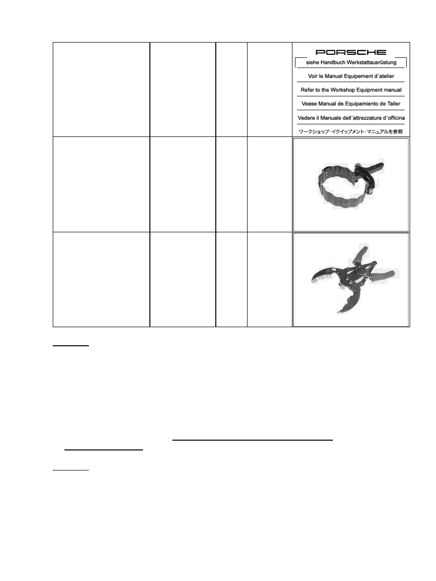
NR.165
universal piston ring
restraining strap, 75 - 125
mm
commercially
available tool
NR.55
piston ring pliers Gr. 1
commercially
available tool
NR.58
Removing pistons, preliminary work
Removing pistons, preliminary work
1. Disassemble engine to crankcase → 100137 Disassembling and assembling engine -
Removing pistons
Diagnostic system: reading out fault memory and activating systems
Removing pistons, preliminary work
257