Porshe 911 (997). Manual - part 12


  Index      Hummer     Porshe 911 997 series - service repair manual 2004-2008 year


Search            


Content   ..  10  11  12  13   ..


Porshe 911 (997). Manual - part 12


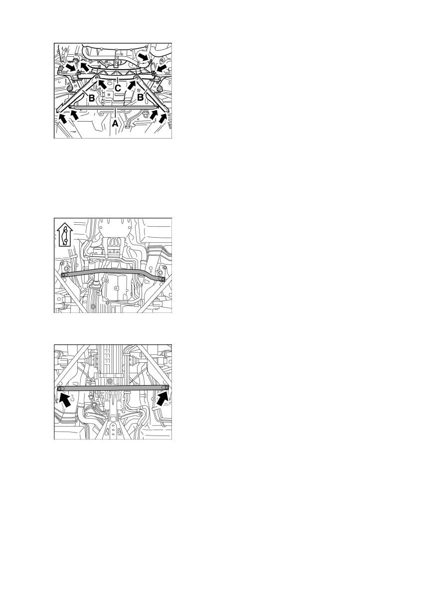
Cross member with accessories

14. Install chassis components:

14.1. Rear cross member: M12 hexagon-collar nuts → Tightening torque: 74 ftlb.

14.2. Diagonal braces on rear cross member: hexagon-head bolt → Tightening torque: 74 ftlb.

14.3. Diagonal brace on rear-axle support: collar nut → Tightening torque: 48 ftlb.

14.4. Diagonal brace to body: hexagon-head bolt → Tightening torque: 48 ftlb.

Transverse strut, Tiptronic

15. Front transverse strut, Tiptronic transmission: hexagon-head bolt → Tightening torque: 48 ftlb.

Transverse strut, manual transmission

16. Transverse strut, manual transmission: hexagon-head bolt → Tightening torque: 48 ftlb.

Diagnostic system: reading out fault memory and activating systems

Installing engine

205

Rear fastening of the stabiliser

17. Installing rear stabiliser → 429019 23 Removing and installing rear stabiliser - installing.

17.1. Engage stabiliser in connecting rod and then fasten to rear-axle support using two hexagonal-head bolts

respectively. → Tightening torque: 17 ftlb.

Stabiliser to connecting rod

18. Position new M10 collar nuts on the connections to the connecting rod. Make sure to counter with a Torx

socket wrench insert when tightening → Stabiliser to connecting rod . → Tightening torque initial
tightening: 37 ftlb.

18.1. Loosen collar nuts and tighten them again. → Tightening torque final tightening: 37 ftlb.

19. Install Tiptronic selector cable → 371519 Removing and installing selector lever cable -

installing.

Shift cables for manual transmission

20. Install shift cables for manual transmission → 341219 Removing and installing shift lever cable -

installing.

Diagnostic system: reading out fault memory and activating systems

Installing engine

206

Connecting servo pressure pipe

21. Connect servo pressure pipe. Push plug into the plug-in coupling in a straight line. The plug must

audibly engage in the holder.

Test tool 9623

Note

The servo line plug-in coupling is designed so that there is an axial play of approx. 1 mm in the
coupling.

• 

22. Inspect correct engagement of the plug coupling with special tool test tool 9623. Insert special tool

into the groove and check that the plug is seated correctly in the coupling by applying slight
pressure. The plug must not slide out.

23. Attach servo return hose to the line using the spring band

clamp.

Note

Allocation of the engine wiring harness round connectors:

• 

Lower plug - grey inner ring

• 

Upper plug - black inner ring

• 

24. Fit engine wiring harness. Turn bayonet lock in clockwise direction (approx. 90°), until the markings of

the round connector and the housing correspond. Fix the wiring harness onto the holder with a new
tie-wrap.

Diagnostic system: reading out fault memory and activating systems

Installing engine

207

Front air-conditioning compressor fastening screw and sleeve

25. Installing air-conditioning compressor: before installing the compressor check whether the aluminium

spacer sleeve -arrow- is inserted. Grease and fit sleeve. Also connect ground cable before installation.

Fastening of the air-conditioning compressor

26. Fit air-conditioning compressor and fasten using three M8 Torx screws (two short ones at the rear, one

long one at the front) -1- . → Tightening torque: 17 ftlb.

Drive belt

27. Fit drive belt. Pay attention to operating direction of used belts. Double-check that the position of the belt

on the belt pulleys is correct.

Subsequent work for installation of engine

Diagnostic system: reading out fault memory and activating systems

 Subsequent work for installation of engine

208


Content   ..  10  11  12  13   ..