Kenworth T680. Manual - part 3


  Index      Kenworth     Kenworth T680 - service repair manual 2014 year


Search            


Content   ..  1  2  3  4  ..


Kenworth T680. Manual - part 3


Precautions:


If you don’t have the proper tools for applying the torque shown below, then the actuator may 
become dysfunctional by applying the wrong torque.  The actuators holes are a critical area and if 
a higher torque is applied, then the holes could fracture causing the actuator to become non-
operational.  


Removal: 

0.


Optional: Remove the mirror system from the truck (see 1).  

1.


Remove the main glass (convex optional) (see 2)

2.


Remove the Housing (see 3)

3.


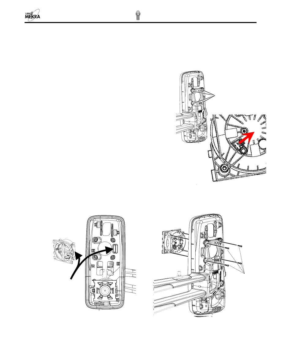
To  remove  the  actuator  connector  from  the  actuator,  push  the 

small 

locking 

lever on the actuator, as shown, and pull the wire harness. 

4.


Remove the 4 Screws 

– Torx T25 from the back of the mirror. 


Installation:


1.


Position the actuator correctly. See figures below. 

2.


Install the 4 screws Torx T25 (torque 2.0 - 2.8 Nm). 

3.


Plug the actuator connector. Make sure it is secured with the lever. 

4.


Re-install the glass, housing and the mirror system on the truck (see 3, 2.1)


Actuator Orientation 

The Actuator flat side 
should match the 
Bezel feature. (Facing 
the truck) 


Torque 

2.0 - 2.8 Nm 

4 screws Torx T25 


Precautions:


If you don’t have the proper tools for applying the torque shown below, then the actuator may 
become dysfunctional by applying the wrong torque.  The actuators holes are a critical area and if 
a higher torque is applied, then the holes could fracture causing the actuator to become 
nonoperational.  


Removal 

0.


Optional: Remove the mirror system from the truck (see 1). 

1.


Remove the glass and the housing (see 2, 3). 

2.


Unplug the actuator (see 4) and the OAT sensor (see 6.3.1) from the bezel. 

3.


Remove the 6 Screws 

– Torx T25 from the back of the mirror and remove the bezel, ensure that the wires 

are not entangled in the bezel when removing the bezel. 

Installation


1.


Position the bezel on the arm so that the holes are aligned and install the 2 lowest screws first.  

2.


Position the actuator and install the 4 screws. 

3.


Torque screws to values as shown in the figure above. 

4.


Plug the actuator connector. Make sure it is secured with the lever. 

5.


Rout the heater wires and OAT sensor (see 6.3.1 ). 

6.


Re-install the glass and housing (see 3, 2) 


Torque: 2.0 - 2.8 Nm 

Torque: 3.0 - 5.0 Nm 


6.1. 

CONTROL CABLE REPLACEMENT 

If your mirror system’s electrical components and/or heating elements fail, then follow the troubleshooting section 
to determine the problem. If the problem can be determined then take the necessary steps to resolve the issue. 

NOTE

: Do 

NOT

 remove the existing control cable at the beginning. This cable will be used to guide the new 

control cable through the mirror’s arm into the correct position. 

Procedure: 

1.


Remove the mirror system from the truck (see 1) and disconnect the connectors carefully. 

2.


Remove carrier glass assemblies (see 2) and the housing (see 3).  

3.


Disconnect all connecters (i.e. actuator, heater foils) and remove the OAT (left hand only) from its location. 

4.


Cut the faulty cable wire just before the first heater foil connecters.  

5.


Insert  this  wire  into  the  flex  guard  (supplied  with  the  replacement  kit)  and  tape  them  tight  with  electrical 
tape. 

6.


Insert the terminals of the new wire control cable at the other side of the flex guard and tape them tight. 

7.


Pull  the  old  control  cable  through  the  arm  until  all  wires  of  the  new  cable  are  outside  of  the  mirror  arm.  
Remove the flex guard (and tape) from the new control cable. 

8.


Insert the terminals ends of the cable into the correct holes on the connector (see 6.4.1) and ensure that 
the holes without wires are plugged with the yellow seal plug. 

9.


Attach the electrical connector back onto the connector housing while pushing the extra cable into the arm 
(see 6.4.3). 

10.


Rout the wire to the different components: Actuator, Heater foil, OAT sensor (left hand only) and reconnect 
the connectors into position (see 6.3). 

11.


Re-install the housing and carrier glass assemblies (see 3 & 2). 

12.


Plug the mirror and truck connectors together, fit the mirror onto the truck and secure it with the four bolts 
as specified. 


OAT SENSOR REPLACEMENT  


The OAT sensor is located on the Left Hand Mirror (driver side). 

Before replacing the sensor, check if it is faulty. Remove the mirror and test the resistance with an ohmmeter 
between terminals 5 & 6 on the connector.  

See the table below to compare the reading against actual temperatures. 


Temp 

deg C 

(deg F)


Min Resistance (kOhms) 

Nom Resistance (kOhms) 

Max  Resistance (kOhms) 

-10

  (13.8) 

52.8 

55.3 

58.0 

-5

  (22.9) 

40.5 

42.3 

44.2 

0

  (32.0) 

31.3 

32.7 

34.0 

5

  (41.1) 

24.4 

25.4 

26.4 

10

  (50.2) 

19.2 

19.9 

20.6 

15

  (59.3) 

15.2 

15.7 

16.3 

20

  (68.4) 

12.1 

12.5 

12.9 

25

  (77.5) 

9.7 

10.0 

10.3 

30

  (86.5) 

7.8 

8.1 

8.3 


Procedure: 

1.


Remove the mirror system from the truck (see 1), carrier glass assemblies (see 2) and the housing (see 3) 
from the mirror. 

2.


Remove the faulty OAT sensor by cutting the green and blu

e wires approximately 1/4” before the sensor 

and appropriately dispose the faulty OAT sensor. 

3.


Strip the ends of the wires on the remaining cable approximately 3/8" from the cut. 

4.


Use butt splice supplied and slide over one of the wires.  

5.


Separate the wire strands in a way that the wires fray as shown in the figure below. 

6.


Push the two wires (new OAT sensor & remaining cable) together to intertwine the two wire strands. 

7.


Slide the butt splice over the combined wires and center it. 

Replacement OAT Sensor 

Butt Splice 


Content   ..  1  2  3  4  ..