Kenworth T680. Manual - part 2
2.1.
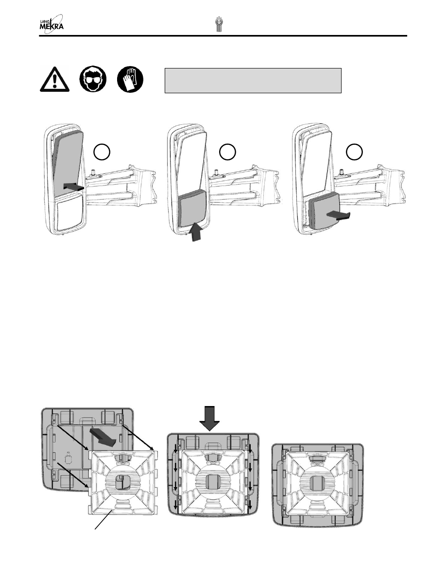
CONVEX MIRROR GLASS
Removal:
1.
Push the main mirror glass inward at the bottom. (The actuator clutch will allow this manual adjustment of
a motorized mirror.) This will provide enough clearance in order to lift up on the convex mirror to
disengage the tabs from the manual socket plate.
2.
With the flat mirror pushed inward, push up on the convex mirror
approximately ½” to disengage the tabs
on the convex carrier plate from the manual socket plate.
3.
The convex mirror can now be removed from the mirror housing.
4.
Disconnect the heating element wires from the heater foil terminals by pulling firmly on the wire
connectors to completely free the convex mirror from the mirror assembly.
Installation:
Install the replacement convex carrier assembly in the reverse operation of it being removed.
5.
Inspect the condition of the heating element wires (corrosion, exposed wire, etc…) before inserting the
connectors onto the heater foil terminals. If they are in good condition, then insert the connectors.
Note:
The manual socket plate is fixed to the bezel. The illustrations shown below demonstrate how to carefully
remove the glass carrier from the manual socket plate.
Fixed to bezel
1
2
3
Warning:
Wear protective gloves and safety
glasses especially when replacing broken glass