Engine International VT365. Manual - part 21


  Index      International     Engine International VT365 - service repair manual 2006 year


Search            


Content   ..  19  20  21  22   ..


Engine International VT365. Manual - part 21


MANIFOLDS AND EXHAUST GAS RECIRCULATION (EGR)

81

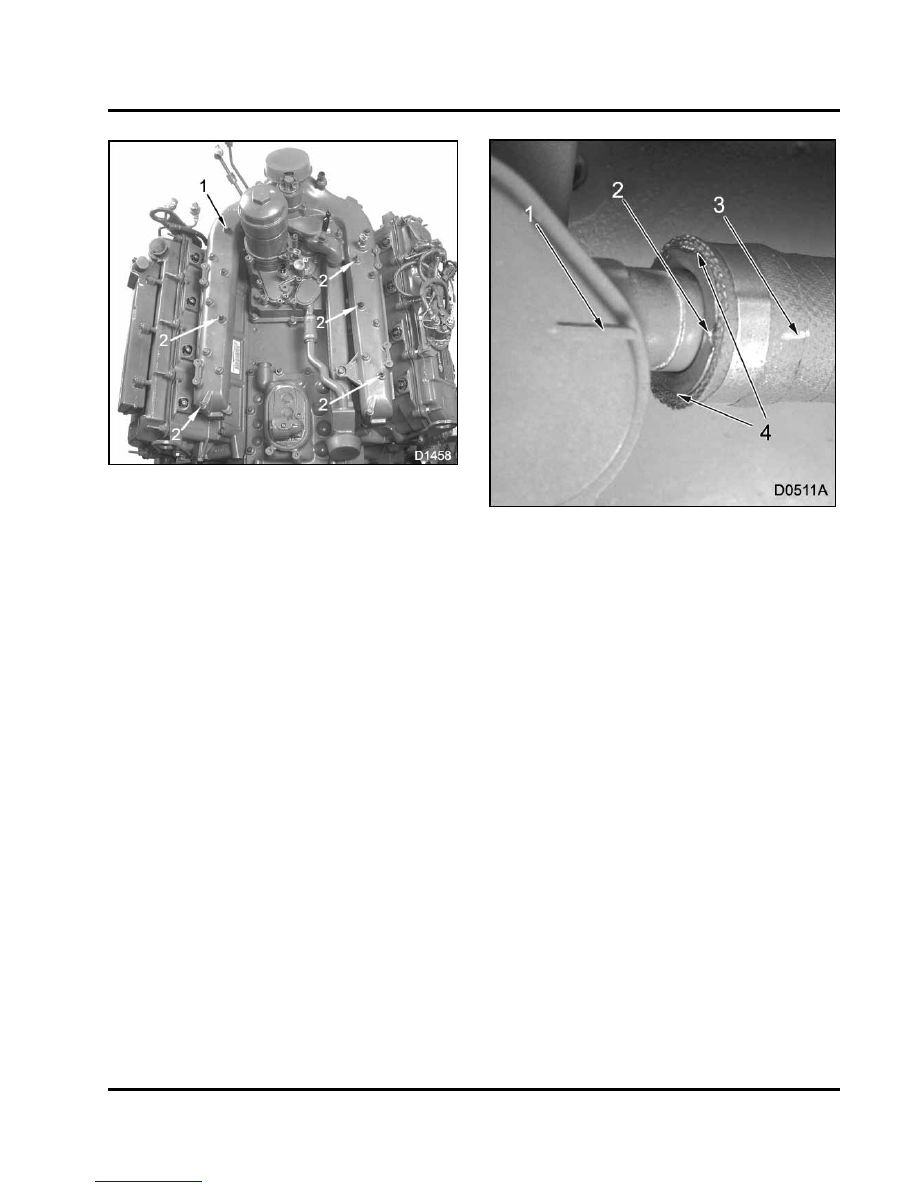
Figure 96 Dog point bolts stud bolts

1.

Bolt (M6 x 95 dog point) (11)

2.

Bolt (M6 x 95) stud (5)

3.

Remove 11 dog point bolts and 5 stud bolts.

Figure 97 EGR coolant inlet coupling

1.

Index feature on coolant supply port cover

2.

Recess

3.

Single index mark

4.

Flat edge representing duel index marks

4.

Align single index mark (if visible) or one of the
recesses on the end of the EGR inlet coolant
coupling (Figure 97) with index feature located on
coolant supply port cover.

This aligns the detentes inside the coupling with
the raised slide-off area of the coolant supply port.

82

MANIFOLDS AND EXHAUST GAS RECIRCULATION (EGR)

Figure 98 EGR coolant inlet coupling removal
from coolant supply port

1.

Index feature on EGR coolant supply cover

2.

Coolant supply port

3.

EGR coolant inlet coupling

5.

Slide the coupling off the port.

6.

Slide EGR coolant inlet coupling toward rear of
engine, away from coolant supply port.

Figure 99 V-clamp on EGR Cooler

7.

Remove V-clamp from EGR cooler.

Figure 100

Intake manifold and EGR cooler

8.

Lift intake manifold assembly straight up to
remove.

9.

Remove and save steel gasket for EGR cooler.

NOTE: The EGR cooler will be bolted to the intake
manifold.

10. Put protective magnetic covers over intake ports

in cylinder head (Table 9).

MANIFOLDS AND EXHAUST GAS RECIRCULATION (EGR)

83

Exhaust Gas Recirculation (EGR) Cooler

Figure 101 EGR cooler retaining bolts

1.

Bolt (M6 x 20) stud (2)

2.

Bolt (M6 x 16)

1.

Put intake manifold on workbench.

2.

Remove two M6 x 20 stud bolts and one M8 x
16 bolt securing the EGR cooler to the intake
manifold.

Figure 102 EGR cooler assembly

1.

EGR cooler to intake manifold gasket

2.

EGR cooler O-ring

3.

Remove cooler assembly and discard gasket.

4.

Remove O-ring.

5.

Remove and save boss grommets.

84

MANIFOLDS AND EXHAUST GAS RECIRCULATION (EGR)

Cleaning, Inspection, and Testing

Intake and Exhaust Manifolds

Intake and exhaust manifolds are one piece castings
and may be cleaned with steam or suitable noncaustic
solvents.

Clean contact areas of EGR O-ring in the intake
manifold, using Injector Sleeve Brush (Table 9). Make
sure carbon above and below contact areas can be
vacuumed from the intake manifold. Vacuum loose
carbon debris.

Exhaust Gas Recirculation (EGR) Valve

Figure 103 EGR valve assembly

1.

Large O-ring

2.

Valve group O-rings (2)

3.

Common pintle shaft

Check the pintle shaft and frame for misalignment.
Remove both O-rings and large O-ring (if not
removed) and discard.

For electrical inspections,

see Engine Diagnostic Manual EGES-240.

Manifold Warp Test for Right and Left Exhaust
Manifold

1.

Use a straightedge and feeler gauge to check
seating surface flatness for right and left exhaust
manifolds.

2.

Check for flatness – across left and right and
diagonally. See “Intake and Exhaust manifolds”
(Table 7).

3.

If specifications are not met, replace right or left
exhaust manifold.

Intake Manifold

Figure 104 Test plates installed on intake
manifold

1.

Install Intake Manifold Pressure Plates (Table 9) .


Content   ..  19  20  21  22   ..