Engine International VT365. Manual - part 18


  Index      International     Engine International VT365 - service repair manual 2006 year


Search            


Content   ..  16  17  18  19   ..


Engine International VT365. Manual - part 18


ELECTRONICALLY CONTROLLED VARIABLE GEOMETRY

TURBOCHARGER (VGT)

69

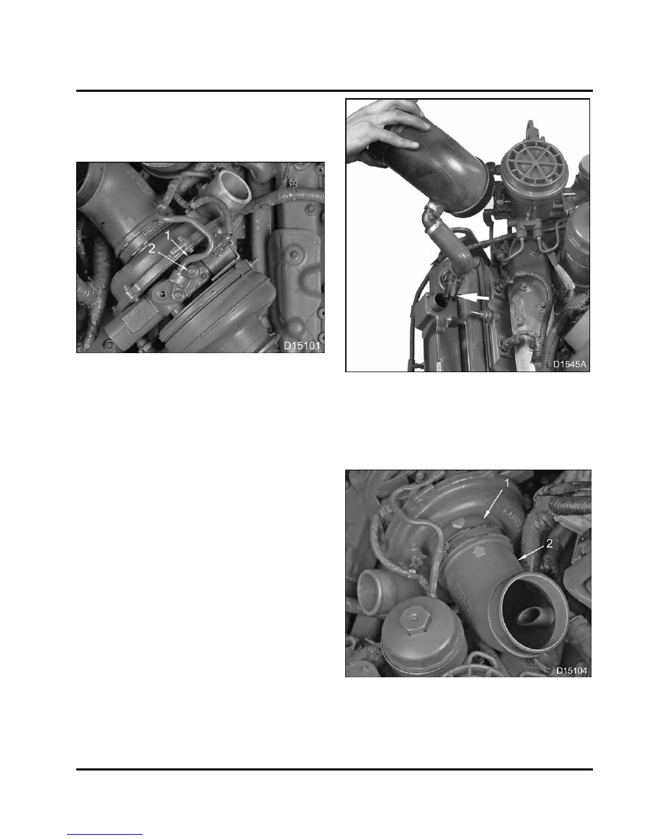
14. Prelubricate the oil inlet hole of the VGT with clean

engine oil and spin compressor wheel several
times to coat bearings with oil. Refill the oil inlet
hole up to oil supply tube mounting surface.

Figure 72 Oil supply tube for VGT

1.

Oil supply tube

2.

Mounting bolt (2)

15. Position oil supply tube over a new gasket and

secure with two M8 x 20 bolts.

16. Tighten to the standard torque (Standard Torques,

page 375).

Alternate tightening between both

bolts until the correct torque is reached.

Figure 73

Breather tube with pitot tube in

crankcase breather

17. Remove cap and press pitot tube in the crankcase

breather until it locks in place.

Figure 74

Air inlet duct to VGT

1.

VGT

2.

Air inlet duct

70

ELECTRONICALLY CONTROLLED VARIABLE GEOMETRY

TURBOCHARGER (VGT)

18. Remove cap and align the arrow on the inlet duct

with the mark on the inlet housing opening on VGT
and press on the VGT.

19. Secure air inlet duct to VGT by tightening hose

clamp to the special torque (Table 5).

Figure 75

Air inlet duct

1.

Lube oil fill extension tube

2.

Breather hose

3.

Air inlet duct

20. Remove cap from the valve cover and thread the

oil fill extension tube in the valve cover and torque
to the special torque (Table 5).

Control Valve (If previously removed)

Figure 76

O-ring lubrication

1.

During reassembly, lubricate new O-rings with
clean engine oil. Make sure O-rings are seated
correctly – not twisted or distorted.

Figure 77

VGT control valve

2.

Install control valve carefully to avoid twisting or
cutting O-rings.

NOTE: Do not use the retaining bolt to draw the control
valve into the housing. Push the VGT control valve in
by hand to seat securely before installing bracket and
bolt.

Figure 78 Retaining bolt for VGT Control valve

1.

VGT control valve bracket

2.

Retaining bolt

ELECTRONICALLY CONTROLLED VARIABLE GEOMETRY

TURBOCHARGER (VGT)

71

3.

Install control valve bracket and retaining bolt and
tighten bolt to standard torque (Standard Torques,
page 375).

Figure 79 VGT control valve

1.

VGT control valve connection

2.

VGT control valve

3.

VGT control valve connector

4.

VGT control valve bracket

WARNING: To prevent personal injury or

death, disconnect the main battery negative
terminal before disconnecting or connecting
electrical components.

1.

Connect the VGT control valve to the electrical
harness.

2.

Reinstall all safety guards, shields, and covers.

3.

Make sure all tools, cleanliness covers, loose
parts, and service equipment are removed from
the engine work area.

72

ELECTRONICALLY CONTROLLED VARIABLE GEOMETRY

TURBOCHARGER (VGT)

Specifications

Table 4 Variable Geometry Turbocharger (VGT) Shaft

Maximum turbine shaft axial end play

0.091 mm (0.0036 in)

Maximum turbine shaft radial shaft movement (play)

0.5 mm (0.02 in)

Special Torque

Table 5 VGT Bolts and Clamps

Air inlet duct hose clamp

4 to 5 N·m (36 to 48 lbf·in)

Oil fill extension tube

14 ± 1 N·m (124 ± 9 lbf·in)

VGT to mounting bracket bolts

31 ± 4 N·m (23 ± 3 lbf·ft)

VGT exhaust adapter V-clamp

12 N·m (108 lbf·in)

Special Service Tools

Table 6 Turbocharger

Description

Tool Number

Cap Kit (All)

ZTSE4610

Dial Indicator with Magnetic Base

Obtain locally

Intake Guard

ZTSE4548


Content   ..  16  17  18  19   ..