Engine International VT365. Manual - part 16


  Index      International     Engine International VT365 - service repair manual 2006 year


Search            


Content   ..  14  15  16  17   ..


Engine International VT365. Manual - part 16


ELECTRONICALLY CONTROLLED VARIABLE GEOMETRY

TURBOCHARGER (VGT)

61

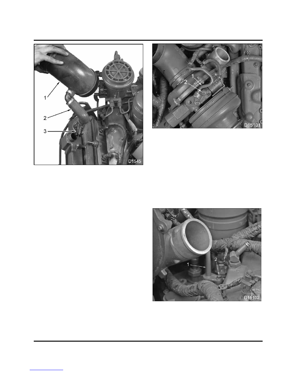
Figure 51 Breather tube and pitot tube

1.

Air inlet duct

2.

Breather hose

3.

Pitot tube

4.

Remove air inlet duct breather hose by turning
breather hose and pitot tube enough to align hold
clips with opening, to remove from the crankcase
breather cover.

5.

Put caps in the opening of the breather cover vent
hole, to keep out foreign material.

Figure 52 Oil supply tube to VGT

1.

Oil supply tube

2.

Mounting bolt (2)

6.

Remove two M8 x 20 bolts from the oil supply tube
mounted on top of the VGT and swing oil supply
tube out of the way.

7.

Remove oil supply tube gasket and discard.

8.

Put a cap over oil supply inlet to the VGT, to keep
out foreign material.

Figure 53 Oil supply tube for VGT to oil cooler
cover assembly

1.

Oil supply tube

2.

Mounting bolt

62

ELECTRONICALLY CONTROLLED VARIABLE GEOMETRY

TURBOCHARGER (VGT)

9.

Disconnect oil supply tube from engine by
removing the M8 x 20 flange head bolt.

10. Remove oil supply tube from oil cooler cover

assembly.

Figure 54

Exhaust adapter V-clamp for VGT

11. Remove exhaust adapter V-clamp.

12. Cover all openings to the VGT when piping is

removed, to keep out foreign material.

Figure 55 Center mounting bolt and spacer for
VGT

13. Remove M8 x 30 flange head bolt and spacer

securing the VGT to the center of mounting
bracket.

Figure 56 Rear mounting bolt for VGT

14. Remove M8 x 30 flange head bolt securing the

VGT to the rear of mounting bracket.

Figure 57 Front mounting bolt and spacer for
VGT

15. Remove one M8 x 30 flange head bolt and spacer

securing the VGT to the front of mounting bracket.

ELECTRONICALLY CONTROLLED VARIABLE GEOMETRY

TURBOCHARGER (VGT)

63

NOTE: If removing the VGT only, cap off oil drain line
to keep out foreign material.

16. Lift the VGT assembly up and off the engine.

Make sure all openings in the VGT assembly are
capped.

NOTE: Use Compressor Inlet Cap and Exhaust Outlet
Cap. (Table 6). If plastic caps are not available, cover
openings with tape.

Figure 58 Oil drain tube for VGT

Figure 59 Removal of oil drain tube for VGT

17. Pull oil drain tube out of high-pressure oil pump

cover.

18. Put a cap over opening in the high-pressure oil

pump cover to keep out foreign material.

19. Remove two O-rings on the oil drain tube and

discard.

Figure 60 VGT bracket bolts

Figure 61 Removal of VGT bracket bolts

20. Remove four M8 x 20 VGT bracket bolts.

64

ELECTRONICALLY CONTROLLED VARIABLE GEOMETRY

TURBOCHARGER (VGT)

Figure 62

VGT mounting bracket

21. Lift up the left side of the bracket first so the right

side can clear the EGR cooler coolant inlet tube.


Content   ..  14  15  16  17   ..