Engine International VT365. Manual - part 15


  Index      International     Engine International VT365 - service repair manual 2006 year


Search            


Content   ..  13  14  15  16   ..


Engine International VT365. Manual - part 15


ELECTRONICALLY CONTROLLED VARIABLE GEOMETRY

TURBOCHARGER (VGT)

57

Description

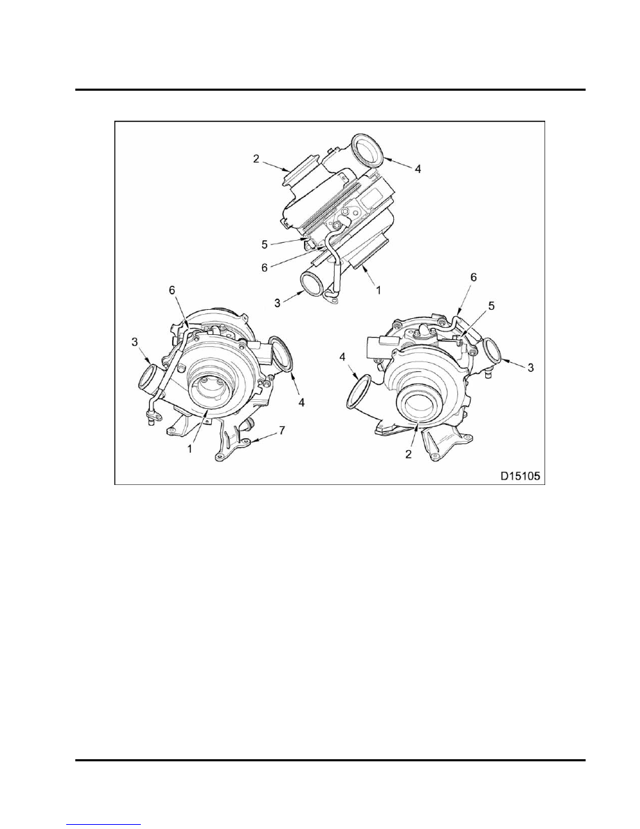
Figure 45 Turbocharger components

1.

Air inlet

2.

Exhaust outlet

3.

Compressor outlet

4.

Exhaust inlet

5.

Turbocharger control valve

6.

Oil supply tube

7.

Turbocharger mounting bracket

Operation

The key feature of the VGT is actuated vanes
in the turbine housing.

The vanes modify flow

characteristics of exhaust gases through the turbine
housing. The benefit is the ability to control boost
pressure needed for various engine speeds and load
conditions.

An additional benefit is lower exhaust

emissions.

The VGT is a closed loop system that uses the
Exhaust Back Pressure (EBP) sensor to provide
feedback to the Electronic Control Module (ECM).
The ECM uses the EBP sensor to continuously

monitor EBP and adjust the duty cycle to the VGT to
match engine requirements.

The solenoid receives a pulse width modulated signal
from the ECM that indicates the on / off time that the
control valve is energized. The control valve directs
lube oil flow to both sides of the piston in the actuator
housing. Directing oil to different sides of the piston
increases or decreases exhaust back pressure.

Actuated vanes are mounted around the inside
circumference of the turbine housing. A unison ring
links all the vanes.

When the unison ring moves,

all vanes move to the same position.

Unison ring

58

ELECTRONICALLY CONTROLLED VARIABLE GEOMETRY

TURBOCHARGER (VGT)

movement occurs when either side of the actuator
piston is pressurized by engine oil.

Exhaust gas flow can be regulated depending on
required exhaust back pressure for engine speed and
load.

The VGT is an exhaust driven centrifugal air
compressor that uses signals from the ECM to control
intake manifold pressure.

The VGT uses a set of

moveable vanes in the turbine housing to change the
flow of exhaust gases through the VGT. These vanes
can be positioned to change the angle or direction
of flow to the turbine wheel depending on engine
operating conditions. As power demands increase,
exhaust gas velocity increases in direct relation, as
does intake manifold boost pressure. Conversely, as
the flow of exhaust gas diminishes, intake manifold
boost pressure is also reduced at the same rate.

Vanes mounted around the internal circumference
of the turbine housing are connected to a unison
ring. When the unison ring moves, all vanes move
to the same position. The unison ring moves, when
either side of the actuator piston receives pressurized
engine oil, regulated by the control valve, part of
a Pulse Width Modulated (PWM) circuit regulated
by the ECM. An increase in duty cycle of the PWM
circuit routes oil through the control valve in a way
that will cause piston movement that increases
manifold pressure. Decreasing the pulse width will

direct oil such that the manifold pressure will be
decreased. The VGT control is a closed loop system
using the EBP sensor to provide feedback to the
ECM. The ECM provides a duty cycle in response to
engine speed, engine load, manifold pressure, and
barometric pressure in order to adjust the duty cycle
to match the requirements of the engine.

The VGT increases power output by supplying
compressed air to the engine.

The internal

components are oil and air cooled.

Engine oil is

circulated through the housing, which acts as a
heat barrier between the “hot” turbine and the “cold”
compressor.

Sleeve Bearings are lubricated by

engine oil. Oil is pumped directly from the oil filter
base, circulates to the VGT housing, and returns
to the sump through an oil drain in the VGT center
housing.

Expanding exhaust gases drive the turbine shaft
assembly to speeds over 100,000 rpm.

Filtered

air entering the compressor side of the VGT is
compressed and delivered through a charge air
cooler. Hot compressed air is cooled, filling the intake
manifold at a pressure higher than atmospheric
pressure. Because considerably more air is forced
into the intake manifold, the results are increased
power, fuel efficiency and the ability to maintain
power at higher altitudes.

ELECTRONICALLY CONTROLLED VARIABLE GEOMETRY

TURBOCHARGER (VGT)

59

Removal

WARNING: To prevent personal injury or

death, read all safety instructions in the “Safety
Information” section of this manual.

WARNING: To prevent personal injury or

death, shift transmission to park or neutral, set
parking brake, and block wheels before doing
diagnostic or service procedures.

WARNING: To prevent personal injury or

death, make sure the engine has cooled before
removing components.

WARNING: To prevent personal injury or

possible death, disconnect the main battery
negative

terminal

before

disconnecting

or

connecting electrical components.

WARNING: To prevent personal injury or

death, do not let engine fluids stay on your skin.
Clean skin and nails, using a hand cleaner, and
wash with soap and water.

Wash or discard

clothing and rags contaminated with engine
fluids.

NOTE: Engine fluids (oil, fuel and coolant) are a threat
to the environment.

Recycle or dispose of engine

fluids according to local regulations. Never put engine
fluids in the trash, on the ground, in sewers or bodies
of water.

Figure 46

Disconnection of VGT control valve

1.

VGT control valve connection

2.

VGT control valve

3.

VGT control valve connector

4.

VGT control valve bracket

1.

Disconnect

the

engine

harness

electrical

connector from the VGT control valve.

VGT Control Valve Removal (If required)

NOTE: The VGT control valve should only be
removed

for

cleaning

and

inspection,

when

troubleshooting VGT problems.

Figure 47 Retaining bolt for VGT control valve

1.

VGT control valve bracket

2.

Retaining bolt

60

ELECTRONICALLY CONTROLLED VARIABLE GEOMETRY

TURBOCHARGER (VGT)

1.

Remove the retaining bolt and control valve
bracket for VGT control valve.

Figure 48 VGT control valve

2.

Remove VGT control valve from turbocharger
center housing.

VGT and Components

Figure 49

Air inlet duct

1.

Lube oil fill extension tube

2.

Air inlet duct

3.

Air inlet duct clamp

1.

Remove oil fill extension tube and put a cap in the
oil fill hole of the valve cover to keep out foreign
material.

Figure 50

Air inlet duct

1.

Turbo air inlet

2.

Air inlet duct

3.

Air inlet duct clamp

2.

Loosen the air inlet duct clamp.

3.

Remove air inlet duct and clamp. Put a cap over
the opening of the VGT air inlet, to keep out
foreign material.


Content   ..  13  14  15  16   ..