Engine International VT365. Manual - part 7


  Index      International     Engine International VT365 - service repair manual 2006 year


Search            


Content   ..  5  6  7  8   ..


Engine International VT365. Manual - part 7


ENGINE SYSTEMS

25

Fuel Management System

Fuel Injection

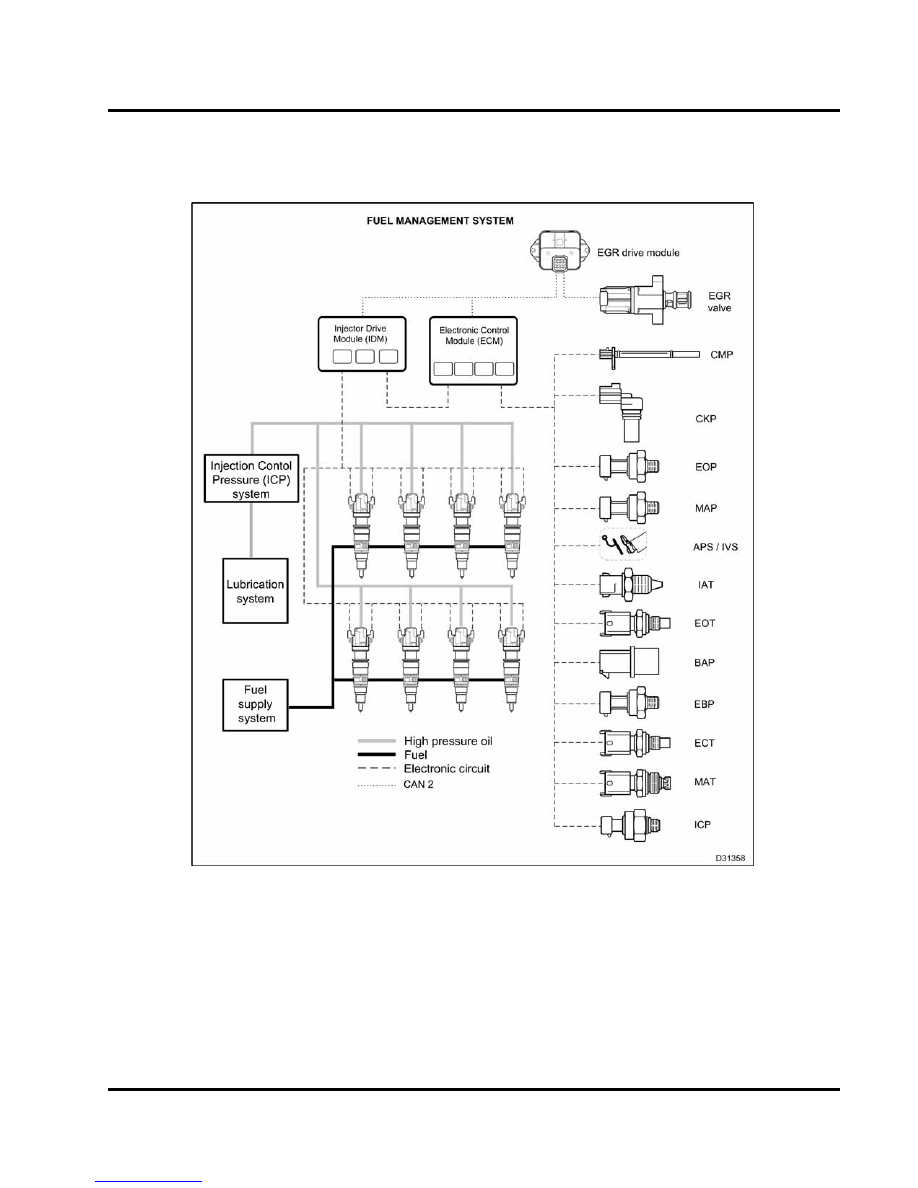
Figure 20 Fuel management system

The fuel management system includes the following:

Injection Control Pressure (ICP) system

Fuel injectors

Electronic control system

Lubrication system

Fuel supply system

26

ENGINE SYSTEMS

Injection Control Pressure (ICP) System

Figure 21 High-pressure oil system

1.

High-pressure oil pump cover
fasteners (8)

2.

Oil rail assembly (2)

3.

High-pressure oil pump cover

4.

Pump-to-cover seal ring

5.

High-pressure oil pump cover
seal

6.

High-pressure oil pump
fasteners (3)

7.

Case-to-head tube assembly (2)

8.

High-pressure oil pump
assembly

9.

Branch tube adapter bolt (2)

10. Branch tube assembly

11. Snap to Connection (STC) fitting
12. Branch tube adapter
13. O-ring
14. IPR valve

High-pressure Oil Flow

A gear driven,

high-pressure oil pump draws

oil through a screen in the oil reservoir for the
high-pressure oil pump. The oil reservoir, in the top
of the crankcase below the oil cooler, is kept full by
the engine lubrication system.

The IPR valve maintains the ICP pressure by dumping
excess oil back to the crankcase.

High-pressure oil from the pump flows through a
branch tube assembly to each case-to-head tube
assembly to each high-pressure oil rail.

High-pressure oil in the oil rails enter the fuel injectors
through sealed ports in the top of the fuel injectors.

When the OPEN coil for each injector is energized, the
injector uses high-pressure oil to inject and atomize
fuel into the combustion chamber. The CLOSE coils
are energized to end injection.

Exhaust oil exits

through two ports in the top of the injector and drains
back to the crankcase.

ENGINE SYSTEMS

27

ICP Closed Loop System

Figure 22 ICP closed loop system

The ICP is a closed loop system that uses the ICP
sensor to provide feedback to the ECM. The ECM
uses the ICP sensor to continuously monitor ICP
and adjust the duty cycle to the IPR to match engine
requirements.

ICP control

Figure 23

ICP control

ICP system operation

The solenoid receives a pulse width modulated signal
from the ECM that indicates the on/off time the control
valve is energized. The pulse is modulated to control
ICP pressure in the range of 3 to 20 MPa (500 to 3,000
psi).

The IPR valve is mounted in the high-pressure
pump cover. The IPR valve maintains the desired
ICP by dumping excess oil out the bottom of the
high-pressure pump cover.

High-pressure oil is routed to the IPR valve and ICP
sensor through the discharge tube and passages in
the high-pressure pump cover.

As the demand for ICP increases, the ECM increases
the pulse width to the IPR solenoid.

When ICP

demand decreases, the ECM decreases the (duty
cycle) to the solenoid, allowing oil to flow from the
drain orifice.

The ECM sets Diagnostic Trouble Codes (DTCs), if
the ICP electrical signal is out of range. DTCs are
also set if an ICP signal corresponds to an out of
range value for injection control pressure for a given
operating condition.

The ECM will ignore ICP signals that are out of range.
The IPR valve will operate from preprogrammed
default values. This is called an Open Loop Operation.

28

ENGINE SYSTEMS

Fuel Injectors

Figure 24 Fuel Injector

1.

CLOSE coil

2.

Control valve body

3.

Intensifier piston

4.

Piston return spring

5.

Plunger

6.

Valve opening pressure spring

7.

Needle

8.

OPEN coil

9.

Spool valve (control valve)

10. Casenut
11. Fuel strainer (3)
12. Nozzle assembly

Fuel injector features

Two 48 volt 20 amp coils control a spool valve that
directs oil flow in and out of the injector. The injector
coils are turned on for approximately 800 (micro
second or millionth of a second). Each injector has
a single four pin connector that passes through the
rocker arm carrier

Injector coils and spool valve

An OPEN coil and a CLOSE coil on the injector move
the spool from side to side using magnetic force. The
spool has two positions:

When the spool valve is open oil flows into the
injector from the high pressure oil rail.

When the spool valve is closed oil drains back to
the crankcase.

Intensifier piston

When the spool valve is open, high pressure oil
enters the injector, pushing down the intensifier piston
and plunger. Since the intensifier piston is 7.1 times
greater in surface area than the plunger, the injection
pressure is also 7.1 times greater than ICP pressure
on the plunger.

Plunger and barrel

Fuel pressure builds between the plunger and the
barrel. When the intensifier piston pushes the plunger
down, the plunger increases fuel pressure in the
barrel 7.1 times greater than ICP. The plunger has
tungsten carbide coating to reduce scuffing and poor
performance.

Injector needle

The injector needle opens inward, off its seat when
fuel pressure overcomes the Valve Opening Pressure
(VOP) - approximately 21 MPa (3100 psi). Fuel is
atomized at high pressure through the nozzle tip.


Content   ..  5  6  7  8   ..