Engine International HS 2.8L. Manual - part 16


  Index      International     Engine International HS 2.8L - service repair manual


Search            


Content   ..  14  15  16  17   ..


Engine International HS 2.8L. Manual - part 16


International HS 2.8L

Pistons and Connecting Rods

7 3

8120081 - 05/02 - Service Manual

INTERNATIONAL ENGINES

3.

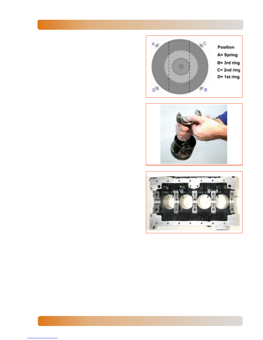
Assembly ring spring in piston 3rd groove
and next ring, with ends in opposite position
from spring ends. Install 2nd and 1st rings
with TOP mark or inner chamfer upwards.
Note that 2nd and 1st grooves rings have
different thickness.

4.

Clearances between rings ends must not be
aligned in the same direction of piston pin or
skirt. Position rings according the illustration.

5.

Assembly new shells on connecting rod
body, correctly positioning locks.

Installation

1.

Set engine block in horizontal position.
Lubricate grooves, inside liners, connecting
rod shells and crankshaft crankpin.

2.

When assembling piston, make sure that the
arrow is aiming the engine front side. Install
connecting rod with the tool nr. 8130646,
avoiding scratching the liner.

3.

Assembly piston in cylinder, using tool nr.
8130647 and a rod of wood to push the
piston.

4.

In turbocharged engines, there is one injector
of lubricant oil for each engine cylinder.
During piston assembly in the cylinder, check
the position of the connecting rod in relation
to the injector, avoiding breaking its injection
pipe.

5.

The positioning of the oil injector inside the
engine block is checked with the engine
viewed from the top, without cylinder head.

International HS 2.8L

Pistons and Connecting Rods

7 4

INTERNATIONAL ENGINES

6.

Complete lubricant oil injector for cylinder
inside and piston pin lubrication is shown
below.

7.

Assembly new shell in connecting rod cap,
correctly positioning locks. Lubricate shell
and crankshaft crankpin.

8.

Assembly cap on connecting rod
corresponding to the cylinder, watching blue
mark on cap, bolt and connecting rod, and
tighten according specified. Manually turn
crankshaft when assembling each
connecting rod. If it is difficult to turn, check
all tightening applied in connecting rods
fixation.

9.

Check axial clearance (0.15 to 0.35 mm)
between assembled connecting rod and
crankpin with dial indicator gauge.

International HS 2.8L

Pistons and Connecting Rods

7 5

8120081 - 05/02 - Service Manual

INTERNATIONAL ENGINES

10. Position piston at TDC. Check piston height

in relation to engine block surface with dial
indicator gauge and tool nr. 8130004, see
CYLINDER HEAD SPECIFICATIONS.

11. Assembly suction, flux pipes and lubricant oil

pan.

International HS 2.8L

Crankshaft

7 7

8120081 - 05/02 - Service Manual

INTERNATIONAL ENGINES

CRANKSHAFT

Removal

1.

Remove engine.

2.

Remove cylinder head and push rods.

3.

Remove accessories support.

4.

Remove oil pan.

5.

Remove timing housing and camshaft.

6.

Remove flywheel housing and flywheel.

7.

Remove pistons and connecting rods.

Disassembly

1.

To disassembly, position engine topside
down. Remove rear oil seal housing and
gasket.

2.

Remove connecting rod caps and shells.

3.

Remove main bearing caps and shells.


Content   ..  14  15  16  17   ..